Wednesday, May 30, 2018

Two Channel digital volume control circuit based on IC MAX5486

Digital Volume Control Circuit Based on IC MAX5486

Digital Volume Control Circuit Based on IC MAX5486 is shown here. MAX5486 is a 40K dual digital volume/balance controller that has a pushbutton interface. The IC has a built-in bias voltage source that eliminated the need of an external circuitry for the same purpose and thereby by reduces external parts count. The IC also has an LED status indicator driver circuit which can be used for driving the status indicator LEDs which indicates the volume level and balance level.


Two Channel digital volume control circuit based on IC MAX5486

The IC MAX5486 can be operated from a single or dual power supply and is available in 24 pin TSSOP package. The volume control circuit based on MAX5486 can be applied in a lot of applications like personal audio systems, handheld audio devices, home theatre systems, car audio systems, computer audio systems etc.

Tuesday, May 29, 2018

Low Pass Filter Circuit using Op-amp TL062 for Subwoofer Pre Amp

Low Pass Filter Circuit using Op-amp

Low Pass Filter Circuit using Op-amp TL062 for Subwoofer Pre Amp: The circuit given here is based on the opamp TL062 from ST Microelectronics. TL062 is a dual high input impedance J-FET opamp which has very low power consumption and high slew rate. The opamp has excellent audio characteristics and is very suitable for this circuit.

Low Pass Filter Circuit using Op-amp TL062 for Subwoofer Pre-amp

Low Pass Filter Circuit using Op-amp TL062 for Subwoofer Pre-amp

Out of the two opamps inside TLC062, first one is wired as the mixer cum pre-amplifier stage. The left and right channel are connected to the inverting input of IC1a for mixing. The gain of the first stage can be adjusted using POT R3. The output of the first stage is connected to the input of the second stage through the filter network comprising of components R5, R6, R7, R8, C4, and C5. The second opamp (IC1b) serves as a buffer and the filtered output is available at the pin 7 of the TLC062.

Low Pass Filter Applications:

  1. LPFs is also used in audio amplifiers to limit the maximum input frequency it’s usually to 20 kHz.
  2. LPF’s are Hmany audio amps use different max high and min low freq values in their filters, 20 Hz to 20 kHz is the range of audio frequencies that most humans can hear.
  3. Low Pass Filters (LPF) is to reduce high-freq noise on signals and make them clearer and this is probably it’s most common use, but there are other uses.

Tags: Audio Amplifiers, Low Pass Filter Circuits, Subwoofer Circuits

Sunday, May 27, 2018

Fire Alarm Circuit using NE555 IC & Thermistor a project for school

Fire Alarm Circuit using NE555 IC & Thermistor

Fire Alarm Circuit using NE555 IC & Thermistor: The Fire alarm Circuit is as simple and uncomplicated so that, it can be easily implemented for a project for school. The thermistor offers a low resistance at high temperature and high resistance at low temperature. This phenomenon is employed here for sensing the fire.


Fire alarm Circuit using NE555 IC & Thermistor

Fire Alarm Circuit using NE555 IC & Thermistor

Thermistors are a type of temperature sensor; their electrical resistance varies as a function of their temperature. They are often used in applications such as fire alarms, refrigerators, ovens, and boilers. They measure temperature by assessing the resistance passing through them and converting it into a temperature reading

Working of Fire alarm Circuit using NE555 IC & Thermistor

The IC1 (NE555) is configured as a free running oscillator at audio frequency. The transistors T1 and T2 drive IC1. The output (pin 3) of IC1 is coupled to the base of transistor T3 (SL100), which drives the speaker to generate an alarm sound. The frequency of NE555IC depends on the values of resistances R5 and R6 and capacitance C2. When thermistor becomes hot, it gives a low-resistance path for the positive voltage to the base of transistor T1 through diode D1 and resistance R2. Capacitor C1 charges up to the positive supply voltage and increases the time for which the alarm is ON.

Read Also: 555 TIMER IC WORKING OF ASTABLE, MONO-STABLE, BI-STABLE MODES AND SPECIFICATIONS

The larger the value of C1, the larger the positive bias applied to the base of transistor T1 (BC548). As the collector of T1 is coupled to the base of transistor T2, the transistor T2 provides a positive voltage to pin 4 (reset) of IC1 (NE555). Resistor R4 is selected s0 that NE555 keeps inactive in the absence of the positive voltage. Diode D1 stops discharging of capacitor C1 when the thermistor is in connection with the positive supply voltage cools out and provides a high resistance path. It also inhibits the forward biasing of transistor T1. Now you can construct this Fire alarm Circuit using NE555 IC & Thermistor a project for school easily.

TDA7240 IC Stereo 20W Amplifier Circuit

20W Amplifier Circuit

TDA7240 IC Stereo 20W Amplifier Circuit: The 20W Amplifier Circuit shown here is based on the TDA7240 IC from ST Microelectronics. The TDA 7240 IC is an integrated audio amplifier IC that can deliver 20 watts of audio output power into a 4ohm load. The IC has minimum external parts count and is available in the 7 pin compact Heptawatt package.


TDA7240 IC Stereo 20W Amplifier Circuit

TDA7240 IC Stereo 20W Amplifier Circuit

The TDA7240 IC Stereo 20W Amplifier Circuit also has a lot of good features like loudspeaker protection, short circuit protection, low noise, low distortion etc. The circuit can be operated from a 12V DC single power supply and this makes it very useful in car audio applications.

Read also: 6 WATT HI-FI AUDIO AMPLIFIER CIRCUIT USING TDA2613 IC

Saturday, May 26, 2018

6 Watt Hi-Fi Audio Amplifier Circuit using TDA2613 IC

6 Watt Hi-Fi Audio Amplifier Circuit using TDA2613 IC

6 Watt Hi-Fi Audio Amplifier Circuit using TDA2613 IC: A 6 watt audio amplifier circuit using TDA2613 is shown here. TDA2613 is an integrated Hi-Fi audio amplifier IC from Philips Semiconductors. The IC is switched ON / switch OFF click proof, short circuit proof, thermally protected and is available in 9 pins single in-line plastic package.


6 Watt Hi-Fi Audio Amplifier Circuit

In the given 6 Watt Hi-Fi Audio Amplifier Circuit, TDA2613 is wired to operate from a single supply. Capacitor C4 is the input DC decoupler while capacitors C5, C6 are power supply filters. Input audio is fed to the non-inverting input through capacitor C4. Inverting input and Vp/2 pins of the IC are tied together and connected to ground through capacitor C3. Capacitor C2 couples the speaker to the ICs output and the network comprising of capacitor C1 and resistor R1 improves the high-frequency stability.

Read Also: 100W MOSFET POWER AMPLIFIER CIRCUIT DIAGRAM

Friday, May 25, 2018

60W-100W, 12VDC to 220VAC Inverter using Transistors

60W-100W Inverter using Transistors

The 60W-100W Inverter using Transistors circuit diagram of a fully transistorized inverter that can drive up to 60W loads. Transistors Q1 and Q2 form a 50Hz astable multivibrator. The output from the collector of Q2 is connected to the input of the Darlington pair formed by Q3 and Q4.


 60W-100W Inverter using Transistors

60W-100W Inverter using Transistors

Similarly, the output of Q1 is coupled to the input of the pair Q5 and Q6. The output from the Darlington pairs drive the final output transistors Q7 and Q8 which are wired in the push-pull configuration to drive the output transformer.

Read more:  100 Watt Inverter Circuit using IC CD4047 and MOSFET

About Inverter Circuit

The circuit can be assembled on a Vero board.
T1 can be a 230V primary to 9-0-9V, 6A secondary transformer.
Transistors Q4, Q6, Q7, and Q8 must be fitted with heat sinks.
Use a 12V, 7Ah battery for powering the inverter.
Slight adjustments can be made on the value of R3 and R4 to get exact 50Hz output.

100 Watt Inverter Circuit using IC CD4047 and MOSFET

100 Watt Inverter Circuit

100 Watt Inverter Circuit using IC CD4047 and MOSFET: The circuit is simple low cost and can be even assembled on a veroboard, CD 4047 is a low power CMOS astable/monostable multivibrator IC. In this 100 Watt Inverter Circuit, it is wired as an astable multivibrator producing two pulse trains of 0.01s which are 180 degrees out of phase at the pins 10 and 11 of the IC.


100W-inverter-circuit

100 Watt Inverter Circuit

100 Watt Inverter Circuit IC CD4047 Pin 10 is connected to the gate of Q1 and pin 11 is connected to the gate of Q2. Resistors R3 and R4 prevents the loading of the IC by the respective MOSFETs. When pin 10 is high Q1 conducts and current flows through the upper half of the transformer primary which accounts for the positive half of the output AC voltage.

Read more:

Wednesday, May 23, 2018

12V Battery Level Indicator Circuit using LM3914 IC

12V Battery Level Indicator Circuit

12V Battery Level Indicator Circuit using LM3914 IC: The LM3914 IC can sense voltage levels and can drive a display of 10 LEDs in dot mode or bar mode. The bar mode and dot mode can be externally set and more than one ICs can be cascaded together to get an extended display.


12V Battery Level Indicator Circuit using LM3914 IC

12V Battery Level Indicator Circuit using LM3914 IC

The LM3914 IC can operate from a wide supply voltage, the brightness of the LEDs can be programmed using an external resistor. The LED outputs of LM3914 IC are TTL and CMOS compatible.

Read more: BATTERY CHARGE CONTROLLER CIRCUIT BY LM324 COMPARATOR IC


100W MOSFET Power Amplifier Circuit Diagram

100W MOSFET Power Amplifier Circuit

100W MOSFET power amplifier circuit based on IRFP240 and IRFP9240 MOSFETs is shown here. The amplifier operates from a +45/-45 V DC dual supply and can deliver 100watt rms into an 8-ohm speaker and 160-watt rms into a 4-ohm speaker. 100W MOSFET power amplifier circuit this is Hi-Fi amplifier circuit is suitable for a lot of applications like general purpose amplifier, guitar amplifier, keyboard amplifier.


100W-mosfet-power-amplifier-circuit

100W MOSFET Power Amplifier Circuit Diagram


Important Note:

Assemble the circuit on a good quality PCB.
Use a +45/-45 V DC, 3A dual supply for powering the circuit.
Power supply voltage must not exceed +55/-55 V DC.
Before connecting the speaker, check the zero signal output voltage of the amplifier and in any case, it should not be higher than 50mV. If it is higher than 50mV, check the circuit for any error. Replacing Q1, Q2 with another set could also solve the problem.
Fit Q7 and Q8 to a 2°C/W heatsink. Both Q7 and Q8 must be isolated from the heat sink using mica sheets. Heat sink mounting kits for almost all power transistors/ MOSFETs of almost all package styles are readily available in the market.
All resistors other than R10, R11 and R19 are 1/4 watt metal film resistors. R10 and R11 are 5W wire wound type while R19 is a 3W wire wound type.

TDA7294 IC 100W Audio Amplifier Circuit Diagram

TDA7294 IC 100W Audio Amplifier Circuit

In the TDA7294 IC 100W Audio Amplifier Circuit, the TDA7294 is configured to provide 100W output power into an 8Ohm loudspeaker at +/- 38V supply. C8 is the input coupling capacitor and the input is applied to the non-inverting input (Pin3) of the IC. C3 and C9 are power supply filter capacitors while C10 and C4 are bypass capacitors. C2 is the bootstrap capacitor.


TDA7294-100W-amplifier-circuit-diagram

TDA7294 IC 100W Audio Amplifier Circuit Diagram

The TDA7294 IC 100W Audio Amplifier Circuit RC network comprising of R1 and C1 improves the high-frequency stability of the amplifier and also prevents oscillations. R2 and C6 set the mute time constant while R3 and C5 set the standby time constant. S1 and the mute switch and S2 are the standby switch. R5 is the input resistance and the amplifiers input impedance has a direct relationship to its value. R4 and R6 are used for setting type closed loop gain and with the used value, the gain is 30dB. C2 is a feedback capacitor and it also provides DC decoupling.

Read more: BA5406 IC 10W STEREO AMPLIFIER CIRCUIT

Tuesday, May 22, 2018

STK4038 IC 60-Watt Amplifier Circuit

STK4038 IC 60-Watt Amplifier Circuit

STK4038 IC 60-Watt Amplifier Circuit: 60-Watt Amplifier Circuit using STK4038 IC. 60-watt audio amplifier electronic project circuit using the STK4038 audio IC Using the STK4038 IC 60-Watt Amplifier Circuit can be designed a very simple high power and efficiency audio power amplifier.


60-watt-amplifier ckt

STK4038 IC 60-Watt Amplifier Circuit

STK4038 IC 60-Watt Amplifier Circuit is a built-in AF power amplifier that will deliver 60 watts of output power into a 4-ohm load. The internal fixed current circuitry reduces switch ON/OFF clicks. The IC supports the addition of external circuits for a thermal shutdown, pop noise reduction, output short circuit protection etc.

Read More: BA5406 IC 10W STEREO AMPLIFIER CIRCUIT

BA5406 IC 10W Stereo Amplifier Circuit

BA5406 IC Stereo Amplifier Circuit

In the BA5406 IC 10W Stereo Amplifier Circuit diagram shown below, BA5406 is configured to deliver to 10watts into 4-ohm loudspeakers at a supply voltage of 9 volts. Capacitor C3 is a power supply filter capacitor. C11 and C12 are input DC decoupling capacitors for the left and right channels. C3 and R2 form a Zobel network for the left output while C6 & R3 forms the same for the right channel. Purpose of the Zobel network is to reduce oscillations and improve the high-frequency stability of the amplifier.


BA5406-stereo-amplifier-circuit

BA5406 IC 10W Stereo Amplifier Circuit

Potentiometers R5 and R6 serve as the volume control for the left and right channels. CapacitorsC4 and C8 couple the outputs of the amplifier to the speakers. C9 and C10 are noise filtering capacitors. C1 and C5 are bootstrap capacitors for the left and right channels

Stereo Headphone Amplifier using LM4910 IC

Stereo Headphone Amplifier

Stereo headphone amplifier based on LM4910 IC  is an audio power amplifier primarily designed for headphone. The IC can be operated from 3.3V and it can deliver 0.35mW output power into a 32-ohm load. The LM4910 has very low distortion ( less than 1%) and the shutdown current is less than 1uA. This low shut down current makes it suitable for battery operated applications.


stereo head phone amplifier LM4910

Stereo Headphone Amplifier using LM4910 IC


Circuit diagram of the Stereo Headphone Amplifier using LM4910 IC is shown above.C1 and C2 are the input DC decoupling capacitors for the left and right input channels. R1 and R2 are the respective input resistors. R3 is the feedback resistor for left channel while R4 is the feedback resistor for the right channel. C3 is the power supply filter capacitor.

Read More: AUDIO AMPLIFIER,

Monday, May 21, 2018

555 Timer IC Working of Astable,Mono-Stable,Bi-Stable Modes and Specifications

555 Timer IC Working

In this article explains 555 Timer IC Working of Astable, Mono-Stable, Bi-Stable Modes and Specifications on www.circuits99.com.

The 555 timer IC is a very cheap, popular and useful precision timing device. The 555 timer IC is an integral part of electronics projects. 555 timer IC it is a simple project involving a single 8-bit micro-controller and some peripherals or a complex one involving system on chips, 555 timer working is involved. These provide time delays, as an oscillator and as a flip-flop element among other applications.


555 timer IC

555 timer IC

The 555 Timer IC generally operates in 3 modes. A-stable, Mono-stable and Bi-stable modes.

1. Astable mode

Astable Mode there will be no stable level at the output. So the output will be swinging between high and low. This character of unstable output is used as clock or square wave output for many applications of 555 IC timer.

2. Mono-stable mode

This Mono-Stable Mode consists of one stable and one unstable state. The stable state can be chosen either high or low by the user. If the stable output is set at high(1), the output of the timer is high(1). At the application of an interrupt, the timer output turns low(0). Since the low state is unstable it goes to high(1) automatically after the interrupt passes. Similar is the case for a low stable monostable mode.

3. Bi-stable mode

In this Bi-Stable Mode, both the output states are stable. At each interrupt, the output changes from low(0) to high(1) and vice versa, and stays there. For example, if we have a high(1) output, it will go low(0) once it receives an interrupt and stays low(0) till the next interrupt changes the status.


Sunday, May 20, 2018

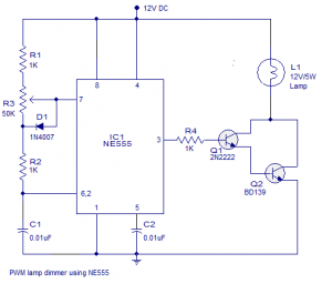
PWM LED Lamp Dimmer Circuit NE555 Timer IC

PWM LED Lamp Dimmer Circuit

PWM LED Lamp Dimmer Circuit NE555 Timer IC is discussed in this article on www.circuits99.com. PWM based dimmers which can hit well over 90% efficiency. Since less amount of power is wasted as heat, the switching elements of PWM dimmers require a smaller heatsink and this saves a lot of size and weight.


PWM LED Lamp Dimmer Circuit NE555 Timer IC

PWM LED Lamp Dimmer Circuit NE555 Timer IC

NE555 timer IC which is wired as an astable multivibrator operating at 2.8KHz forms the heart of this PWM LED Lamp Dimmer Circuit NE555 Timer IC. Resistors R1, R2, POT R3 and capacitor C1 are the timing components. The duty cycle of the NE555 Timer IC’s output can be adjusted using the POT R3. NE555 Timer IC higher the duty cycle means higher the lamp brightness and lower the duty cycle means lower the lamp brightness.

In PWM LED Lamp Dimmer Circuit Diode D1 by-passes the lower half of the POT R3 during the charging cycle of the astable multivibrator. This is done in order to keep the output frequency constant irrespective of the duty cycle. Transistors Q1 and Q2 form a Darlington driver stage for the 12V lamp. Resistor R4 limits the base current of transistor Q1.

Tags:

555 timer pin diagram

555 timer circuit diagram

555 timer working

555 timer monostable

555 timer applications

555 timer pdf

555 timer internal circuit

ic 555 block diagram


Car Stereo Audio Amplifier Circuit using TDA1553 IC

Audio Amplifier Circuit TDA1553 IC

Car Stereo Audio Amplifier Circuit using TDA1553 IC is a monolithic Class-B audio amplifier which contains 2 x 22-watt amplifiers in bridge tied load configuration. The amplifier operates from 12V DC. This circuit of a car stereo amplifier based on TDA1553.


car-stereo-audio-amplifier-circuit

Car Stereo Audio Amplifier Circuit using TDA1553 IC

Car Stereo Audio Amplifier Circuit operates from 12V DC and is developed internationally for car audio applications. The IC also has a load of good features like short circuit protection, load dump protection, reverse polarity protection, loudspeaker protection etc.

Read More:

LM358 IC OP-AMP AUDIO AMPLIFIER

Saturday, May 19, 2018

12V / 3A Regulated Power Supply Circuit by IC CA3085

12V / 3A Regulated Power Supply Circuit

The 12V / 3A Regulated Power Supply Circuit uses monolithic IC CA3085 voltage regulator in the 8-lead TO-5 package. Its salient features include good load and line regulation, output current up to 100mA output short-circuit protection and lower input voltage.


12V-3A-Power-Supply-circuit

12V / 3A Regulated Power Supply Circuit by IC CA3085

Here we provide a powerful 12V / 3A regulated power supply circuit. Of course, the circuit provides a 12V regulated power supply with output current up to 3 amperes. It is specially designed for use with 2m handheld rigs with a linear power amplifier,12v 3a transformerless power supply

Z2C Tube Power supply Circuit

Z2C Tube Power supply Circuit

Z2C is the rectifier tube in power supply with tube above require a supply voltage for the filaments taken from the other side of the transformer secondary. Power supply with the Z2C tube is a power supply that adapts used as a substitute power supply for power amplifier tubes with a diode.
Power Supply-z2c circuit

Wednesday, May 16, 2018

TPA3122d2 15 Watts Class D Audio Amplifier Circuit Diagram

TPA3122d2 15 Watts Class D Audio Amplifier

TPA3122d2 15 Watts Class D Audio Amplifier is used as a class D audio amplifier and can develop up to 15W of power at 10% distortions. The main advantage of using a class D amp, especially TPA3122d2 IC is the fact that another advantage of this IC doesn’t need a heatsink because it has a high efficiency.


TPA3122-audio-amplifier-circuit

TPA3122d2 15 Watts Class D Audio Amplifier Circuit

TPA3122d2 15 Watts Class D Audio Amplifier can provide enough power for what I need even though it can output only 8W with 1% distortions on a 4Ω speaker. The main reason I would choose this instead of a class A or B IC TPA3122d2 is the fact it doesn’t need a heatsink, so the whole amplifier will be lighter in weight and cheaper.

Sunday, May 13, 2018

Sine Wave To TTL Converter Circuit Diagram

Sine Wave To TTL Converter Circuit Diagram

Sine Wave To TTL Converter is a series that we can use to change the sine wave signal with a pulse shape with the same frequency with TTL logic level that we are ready to use in coding the data digitally. The series of Sine Wave To TTL Converter can be used to convert sine wave signal to form a TTL of frequency 100KHz to 80MHz at the level of 100mV – 2V. The series of Sine Wave To TTL Converter uses a 5VDC voltage source.
 Sine Wave To TTL Converter Circuit
Sine Wave To TTL Converter circuit
The series of Sine Wave To TTL Converter was built from transistor T1 gets base bias from R3, R4, and R5. If the series Sine Wave Converter This TTL To get the input sine signal with a minimum level of 100mV, the circuit Sine Wave To TTL Converter This will generate an output signal with TTL level square wave

4-Channel Watt Car Audio Amplifier by using LV47004P audio IC

Car Audio Amplifier by using LV47004P audio IC

This car audio amplifier electronic project by using  LV47004P audio IC, specially designed for car audio applications. The LV47004P audio IC is manufactured by Sanyo Semiconductors and is a 4-channel BTL power amplifier that is developed for car audio system.

Pch DMOS in the upper side of the output stage and Nch DMOS in the lower side of the output stage are complimentary.
High power and high-quality sound are realized by that.

This IC incorporates various functions like standby switch, muting function, and various protection circuit; necessary for car audio system. Also, the LV47004P audio IC has a self-diagnosis function

This 4×24 watt car audio amplifier based on an LV4700P IC circuit can operate from a 9 to 16 volts DC power supply circuit but typically is recommended with a 14.4 volt DC power supply.


car-audio-amplifier

4-Channel Watt Car Audio Amplifier

The output power that can be provided by this car audio amplifier circuit is around 24 watt per channel with the 10 %, on a 4 ohms load. In same conditions, this 4×24 watt car audio amplifier based on LV4700P can provide a maximum output power of 17 watts per channel with THD 1 %.
As you can see in the schematic circuit, the design of this power amplifier project is very simple, requiring few external electronic parts.
By varying the value of input capacitor, a low-frequency characteristic can be improved.

Please turn on the muting function simultaneously with a power supply on when the amplifier is turned on. Next, turn off the muting function after the output DC potential stabilization. When the amplifier is turned off, turn off the power supply after turning on the muting function.
To prevent damage due to overheating process the LV47004P audio IC must be heatsinked.

Friday, May 11, 2018

Adjustable Power Supply for 50V, 15A | Variable DC Power Supply Circuit Diagram

Adjustable Power Supply

the wiring diagram of the 50V, 15A A adjustable power supply provides a similar amount of current through the parallel work of four power transistors, which must be mounted on a good heatsink. The voltage adjustment is performed in integrated LM317, which also must be dissipated mechanically.

Variable DC Power Supply Circuit


50v /15a adjustable power supply

The bridge rectifier should be at least 50 volts and 20 amps. It is recommended to use metal mounted on the heatsink.

Wednesday, May 9, 2018

Low Noise Subwoofer Power Amplifier Circuit by TDA8561Q IC

Low Noise Subwoofer Power Amplifier

Low Noise Power Amplifier Circuit for subwoofer This circuit recommended audio systems of cars and home theater technology for low noise and high base requirements. The power amplifier used is an integrated class-B output amplifier. It contains 4×12W single-ended (SE) or 2×24W bridge-tied load (BTL) amplifiers. The output speaker is connected in BTL configuration in this system for better quality.


Subwoofer Power Amplifier Circuit by TDA8561Q IC

The above circuit components are same as given in circuit diagram of power amplifier circuit and ratings also same. Low-noise JFET-input operational amplifiers TL072 (IC1), car radio power amplifier TDA8561Q (IC2) and transistors BC547 (T1 and T2). IC2 has two 24W BTL output channels, one of which is connected to loudspeaker LS1. BTL is an output configuration for audio amplifiers, a form of impedance bridging where two channels of a stereo amplifier are fed the same audio signal.

TDA2822M IC Mini Amplifier Circuit Diagram

Mini Amplifier Circuit

Mini Amplifier:

This mini amplifier is TDA2822M IC making it simple and compact in size and also used for laptop speaker amplifiers. This circuit can operate small voltage 3 volts to 9 volts and also carry with us.
mini amp by tda2822m

Description:

The input is taken from pin no.4 through variable resistor VR1 and capacitor C4.
The variable resistor VR1 is used to select the Range of signal. Capacitor C2 and C6 are used to filter and quality whereas capacitor C3 and C5 are used to bias the audio frequency.
The output of amplifier IC is obtained at pin 1 where resistor R4 and capacitor C8 is used as feedback component. The output is given to the loudspeaker through capacitor C7 in order to produce sound.
Components:
  • Resistors    –        R1 = 10 KΩ
    R2 = 47Ω
    R3 = 220Ω
    R4 = 1Ω
    VR1 = 50 KΩ
  • Capacitors  –       C1 = 470 pF
    C2 = 220 µF/10V
    C3 = 100 µF/10V
    C4 = 0.1 µF
    C5 = 10 µF/10V
    C6, C7 = 470 µF/10V
    C8 = 0.1 µF
    Semiconductors-  IC1 = LM1895N
    Miscellaneous  –  LS1 = 4Ω/1W speaker
    Tags: mini amplifier circuit board, 3v audio amplifier circuit diagram, 10w mini audio amplifier circuit, 6v audio amplifier circuit, how to make a mini amplifier at home, audio amplifier circuit diagram with layout, simple amplifier circuit diagram using transistor, a 20-watt amplifier circuit

50 Watt Amplifier Circuit pcb diagram

50 Watt Amplifier

50 Watt Amplifier Circuit is the article explaining  Amplifier Circuit on circuits99.com it is the point to where circuits like audio amplifiers, power supply circuits and more…

50 Watt Amplifier

50 Watts Amplifier Circuit Diagram

Tags: 50 watts amplifier PCB diagram, 50w subwoofer amplifier circuit, 12v audio amplifier circuit diagram, 50-watt stereo amplifier, 12v transistor amplifier circuit, 50w audio amplifier circuit, 50-watt amplifier kit, 12v 100w amplifier circuit.

IR Sensor Module Working with Arduino

IR Sensor Module Working Introduction Introduction : Start with a brief introduction to the IR Sensor Module and its applications. Mention t...