Monday, July 30, 2018

How to Repair Computer Speakers Power Problem | How to Fix Computer Speaker

How to Repair Computer Speakers Power Problem

How to Fix Computer Speaker

In this video explaining How to Repair Computer Speakers Power Problem those can easily find out the problem where can occurs by using this video tutorial by conducting simple steps. If your audio devices such as computer speakers, home theatres, and all electronic equipment can fix problems in the following manner.

  1. First, we should check the power cord before going to open the circuit, plug in the power cord and switch ON the supply. Now check the output of the power card by using the multimeter by selecting AC 750 voltage Range and check it.
  2. Check the output of the Transformer ( secondary winding) if it fails then the output voltage shows Zero. then we should change the transformer, the voltage rating must be the same.

In many small electronic devices failure damage of T/F, transistors,  capacitors from improper voltages ie. input voltage is greater than the required voltage.


Monday, July 23, 2018

FM Transmitter Bug Circuit Diagram Using BC548 Transistors

FM Transmitter Bug Circuit Diagram


FM Transmitter Bug ckt
FM Transmitter Bug


This small FM Transmitter Bug Circuit Diagram uses a Hartley type oscillator. Normally the capacitor in the tank circuit would connect at the base of the transistor, but at VHF the base-emitter capacitance of the transistor acts as a short circuit, so in effect, it still is. The coil is four turns of 18swg wire wound around a quarter inch former. The aerial tap is about one and a half turns from the supply end. Audio sensitivity is very good when used with an ECM type microphone insert. FM Transmitter Bug using with BC548 Transistors

AM (amplitude modulation) Transmitter Circuit Diagram

AM Transmitter Circuit Diagram

              radio transmitter block diagram

It is illegal to operate an AM Transmitter without a license in most countries. AM Transmitter Circuit Diagram is deliberately limited in power output but will provide amplitude modulation (AM) of voice over the medium wave band.

The circuit is in two halves, an audio amplifier, and an RF oscillator. The oscillator is built around Q1 and associated components. The tank circuit L1 and VC1 are tunable from about 500kHz to 1600KHz. These components can be used from an old MW radio, if available. Q1 needs regenerative feedback to oscillate and this is achieved by connecting the base and collector of Q1 to opposite ends of the tank circuit.

The 1nF capacitor C7, couples signals from the base to the top of L1, and C2, 100pF ensures that the oscillation is passed from collector to the emitter, and via the internal base-emitter resistance of the transistor, back to the base again. Resistor R2 has an important role in this circuit. It ensures that the oscillation will not be shunted to ground via the very low internal emitter resistance, re of Q1, and also increases the input impedance so that the modulation signal will not be shunted. The oscillation frequency is adjusted with VC1.

Q2 is wired as a common emitter amplifier, C5 decoupling the emitter resistor and realizing the full gain of this stage. The microphone is an electret condenser mic and the amount of AM modulation is adjusted with the 4.7k preset resistor P1. An antenna is not needed, but 30cm of wire may be used at the collector to increase transmitter range. am receiver block diagram

Tuesday, July 10, 2018

Simple Single Chip Metal Detector Circuit based on IC CS209A

Simple Single Chip Metal Detector Circuit

This is a simple single chip metal detector circuit based on IC CS209A  which is from the Cherry Semiconductors. A 100uH inductor coil is used to sense the presence of metal. The IC CS209A has a built-in oscillator circuit and the coil L1 forms a part of its external LC circuit which determines the frequency of oscillation.


simple single chip metal detector circuit

simple single chip metal detector circuit

The 100uH inductance of the coil change in the presence of metals and the resultant change in oscillation is demodulated to create an alarm. The LED gives a visual indication too. This Simple Single Chip Metal Detector Circuit can sense metals up to a distance of few inches.

Simple Single Chip Metal Detector Circuit notes

Assemble the circuit on a general-purpose PCB.
The switch S1 can be a slide type ON/OFF switch.
The IC must be mounted on a holder.
The POT R1 can be used to adjust the sensitivity of the circuit.

Voice Modulator Circuit using IC HT8950A

Voice Modulator Circuit

This is a multi-voice modulator circuit using IC HT8950A from Holtek Semiconductors. The IC HT8950A is capable of creating 7 upward or downward steps on the frequency of the input voice at a rate of 8Hz. The Voice modulator circuit using IC HT8950A also two special variation effects namely Vibrato mode and Robot mode.


IC HT8950A

Voice modulator circuit

This Voice modulator circuit finds a lot of application in systems like telephone, speech processors, toys, mixers etc. A microphone is used to pick up the input voice. Push button switches S2 and S3 of  IC HT8950A can be used for the upward and downward frequency stepping. Push button switch S1 can be used to activate Vibrato mode and push button switch S4 can be used to activate the Robot mode. IC HT82V733 (also from Holtek) is used to amplify the output of the voice modulator. LED D1 indicates the voice level.

Voice modulator circuit using IC HT8950A notes

The circuit can be assembled on a Vero board.
Do not give more than 4.5v to the circuit.
Switches S1 to S4 can be miniature pushbutton switches.
S5 can be a miniature ON/OFF switch.
K1 can be an 8-ohm speaker.
IC1 and IC2 must be mounted on holders.

Sunday, July 8, 2018

Led Torch Light Using IC MAX660 Led Circuit Diagram

Led Torch Light Using IC MAX660

This is a simple Led Torch Light Using IC MAX660 Led Circuit Diagram from MAXIM semiconductors. The MAX 660 IC is a CMOS type monolithic type voltage converter IC for electronics projects. The MAX 660 IC can easily drive three extra bright white LEDs.The LEDs are connected in parallel to the output pin 8 of the IC. The circuit has a good battery life. The switch S1 can be a push to ON switch. It’s not like a flashlight.


Led Torch Light Using IC MAX660

Led Torch Light Using IC MAX660 Led Circuit Diagram

Notes for Led Torch Light Circuit Diagram

Assemble the circuit on a general-purpose PCB.
The IC must be mounted on a holder.
The circuit can be powered from two torch cells connected in series.
The capacitors C1 and C2 must be Tantalum type.
The diodes D1 to D3 must be of 1N4148

Monday, July 2, 2018

Simple Touch Sensor Circuit

Touch Sensor Circuit

The Simple Touch Sensor Circuit is Designed with three components such as a resistor, a transistor, and a light emitting diode. Here, both the resistor and LED connected in series with the positive supply to the collector terminal of the transistor. Select a resistor to set the current of the LED to around 20mA.


Simple Touch Sensor Circuit

Simple Touch Sensor Circuit

Now Simple Touch Sensor Circuit gives the connections at the two exposed ends, one connection goes to the +ve supply and another goes to the base terminal of the transistor. Now touch these two wires with your finger. Touch these wires with a finger, then the LED lights up.


Simple Rain Alarm Circuit Diagram

Rain Alarm Circuit Diagram

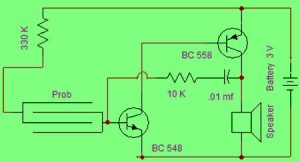
The Simple Rain Alarm Circuit Diagram is used to give an alert when it’s going to rain. This circuit is used in homes to guard their washed clothes and other things that are vulnerable to rain when they stay in the home most of the time for their work. The required components to build this circuit are probes. 10K and 330K resistors, BC548 and BC 558 transistors, 3V battery, 01mf capacitor, and speaker.

Circuit Diagram

Simple Rain Alarm Circuit Diagram

Simple Rain Alarm Circuit Diagram

Whenever the rainwater comes in contact with the probe in the above circuit, then the current flow through the circuit to enable the Q1 (NPN) transistor and also Q1 transistor makes Q2 transistor (PNP) to become active. Thus the Q2 transistor conducts and then the flow of current through the speaker generates a buzzer sound. Until the probe is in touch with the water, this procedure replicates again and again. The Simple Rain Alarm oscillation circuit built in the above circuit that changes the frequency of the tone, and thus tone can be changed.

Simple Temperature Monitor Circuit

Temperature Monitor Circuit

This Simple Temperature Monitor Circuit gives an indication using an LED when the battery voltage falls below 9 volts. This circuit is ideal to monitor the level of charge in 12V small batteries. These batteries are used in burglar alarm systems and portable devices. The working of this circuit depends on the biasing of the base terminal of the T1 transistor.


Simple Temperature Monitor Circuit

Simple Temperature Monitor Circuit

When the voltage of the battery is more than 9 volts, then the voltage on base-emitter terminals will be same. This keeps both transistors and LED off. When the voltage of the battery reduces below 9V due to utilization, the base voltage of T1 transistor falls while its emitter voltage remains same since the C1 capacitor is fully charged. At this stage, the base terminal of the T1 transistor becomes +ve and turns ON. The C1 capacitor discharges through the LED

IR Sensor Module Working with Arduino

IR Sensor Module Working Introduction Introduction : Start with a brief introduction to the IR Sensor Module and its applications. Mention t...