Saturday, October 30, 2021

PUBG Mobile Lite Apk File Download | PUBG Lite PC Download

PUBG Mobile Lite

PUBG Mobile Lite

After the PUBG ban for PUBG Mobile Lite, a lot of research has been done on the internet in India. Let us know that you cannot download PUBG Mobile Lite from Google Play Store. For this, you need to use other software like APK and OBB files. We will give you all the information you need about APK and OBB files. All the necessary information about how to download PUBG Mobile Lite APK is provided to you in the article below.

PUBG Mobile Lite Download [APK+OBB] PUBG Lite PC Installation Guide

Download PUBG Mobile Lite [APK + OBB] PUBG Lite PC installation guide is here. See the details of the PUBG Lite mobile game right now on this page. Now, you don’t have to travel the internet a lot to download PUBG Mobile Lite. As we all know, in September of last year, the Indian government banned 117 other Chinese apps, including PUBG. After the ban on PUBG, PUBG Lovers began to search the internet for other options for the game of Battle Royale. Some gamers have downloaded the light version of the PUBG game. For PUBG Mobile Lite, this PUBG Mobile Lite usually works on 1GB mobile as well, so you don’t need to take more GB of mobile.

How to Install PUBG Mobile Lite APK File

  • Download the given PUBG Mobile Lite APK file, go to Mobile data file download settings, and select Unknown sources.
  • Now install the APK file on your mobile and follow the steps below.
  • Once the file is installed, find the Zarchiver app on the Google Play Store and install it on your mobile.
  • Now after installing the downloaded Zarchiver app, extract the file from an SD card or Android memory.
  • Now you can easily enjoy the PUBG Mobile Lite game on your mobile.

The download and installation information given above is based on information available on the Internet. The information given turns out to be incorrect, just a coincidence. You can download the PUBG Mobile Lite APK file to your mobile using the information you provided. PUBG Lite will be relaunched soon in India. Hear that PUBG Lite will be released by Microsoft in India this time.

PUBG Mobile Lite OBB File Download

Before you download the PUBG Mobile Lite OBB file, you need to make sure your device supports version 4.0. If your phone device is not version 4.0, you will not be able to enjoy this game on your mobile. We fully help you to download PUBG Mobile Lite via OBB file. You can easily play PUBG Mobile Lite even on your low RAM mobile

How To Download PUBG Mobile Lite OBB File

  • First, download PUBG Lite on your mobile via the APK download link below.
  • Now save the PUBG Lite OBB file with any name on your mobile.
  • Unzip the downloaded OBB file and run it on your mobile.
  • After running, the OBB file will activate PUBG Mobile Lite on your phone.
  • Now you can play PUBG Lite games on your mobile with an OBB file.

PUBG Lite PC Download

Before playing or installing a PUBG Lite PC game, you should check the system requirements for that game. Failure to do so may damage your mobile or PC. We provide you with a PUBG Lite PC installation guide along with system requirements information to play the PUBG game.

How To Install PUBG Lite PC

  • To install PUBG Lite on PC, you need to download PUBG Lite Launcher from the official website first.
  • In the next step, you need to download the PUBG Lite game on your PC and create a new account after downloading it.
  • Now open the downloaded folder on your PC, click on Install PUBG Lite Launcher and start installing PUBG Lite on your PC process.
  • You need to restart the game after the installation of PUBG Lite on the PC is complete.
  • Once the game has restarted, you will need to log back into your account.
  • After logging in, you can enjoy PUBG Lite on your PC.
Apk File DownloadClick Here

Wednesday, October 27, 2021

Potential Transformer | Applications of Potential Transformer and Working

Potential Transformer

The Potential Transformer is a passive electromagnetic device that works on the principle of electromagnetic induction, which transfers electrical energy magnetically from one circuit to another. It has two coils which are one primary and one secondary. The two windings (coils) are magnetically connected to each other without any magnetic core and are electrically separated.

The transformer transmits electrical energy (voltage/current) from one winding to another winding (coil) by mutual induction. The transformer transfers the electrical power from one winding to another winding without changing the frequency. Transformers are classified into two types based on the structure of the core, such as core-type transformers and shell-type transformers. These are step-up transformers and step-down transformers. Different types of transformers are used in AC circuits, such as power transformers, potential transformers, three-phase transformers, and autotransformers.

What is a Potential Transformer?

A potential transformer is a step-down transformer that lowers the voltage of a high voltage circuit to a low level to measure it. These are connected through or in parallel to the monitored line.

An electromagnetic device used to convert a high voltage of a circuit into a low voltage is called a potential transformer. The output of a low voltage circuit can be measured with voltmeters or wattmeters. These can increase or decrease the voltage levels of the circuit, without changing its frequency and windings. Working principle, the structure of potential transformer is the same as the power transformer and conventional transformer.

Potential Transformer Symbol

potential transformer symbol

Potential Transformer Symbol

Potential Transformer Circuit Diagram

potential transformer

Potential Transformer Circuit Diagram

Potential Transformer Working

A potential transformer connected to the power circuit on which the voltage is to be measured is connected between phase and earth by using a voltmeter. That is, the primary winding of the potential transformer is connected to the high voltage circuit, and the secondary winding of the transformer is connected to the voltmeter. Due to mutual excitation, the two windings are magnetically attached to each other and act on the principle of electromagnetic induction.

According to the convention transformer, the transformation ratio is V1/V2 = N1/N2

V2 = V1N2/N1

‘V1’= voltage of the primary winding

‘V2’ = voltage of the secondary winding

‘N1’= number of turns in the primary winding

‘N2’= number of turns in the secondary winding

Types of Potential Transformers

These are classified into outdoor and indoor potential transformers

1. Outdoor Potential Transformers

2. Indoor Potential Transformers

Outdoor Potential Transformers

There can be single or 3-phase potential transformers that are available for different ranges of operating voltages which are used for outdoor relaying and metering applications.

Electromagnetic or Wound Type Conventional Potential Transformer

These are Up to 33KV, these are of electromagnetic type single and three-phase voltage transformers are used.

33KV single-phase outdoor potential transformers can be two types electromagnetic type and capacitive voltage transformer (CVT) are used.

Indoor Potential Transformers

They are also available as single-phase or three-phase mold and magnetic type PTs. The mounting mechanism can be of the fixed or withdrawable type. In these types of PT, all parts of the primary winding are isolated from the earth with their rated insulation capacity. These are designed to operate relays, measuring instruments, and other control devices in the indoor service with high accuracy.

Applications of Potential Transformers

  • Used for the protection of impedance in the generators
  • Used in Distance protection of feeders
  • Used in synchronization of generators and feeders.
  • For Electrical protection systems
  • Used for Electrical Metering systems
  • Used as protection voltage transformers
  • Uses in power line carrier communication circuits

Battery Charge controller Circuit by LM324 IC Comparator | Applications of LM324 IC

Battery Charge Controller Circuit

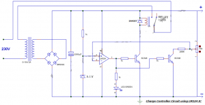
The charge controller circuit for the battery does not bother you when you worry about changing the charger with different battery levels, the main advantages are an improved lifetime and low power consumption since it turns off the charger when the battery is fully charged. So far, we have published a simple battery charge controller circuit using 555 IC, where many of our readers commented that they found it difficult to set threshold levels and also that it seemed more difficult to analyze the operation of the threshold.

Read Also: 24v lead acid battery charger circuit diagram

Battery Charge Controller Circuit by LM324 Comparator IC

Battery Charge controller

Battery Charge Controller Circuit Diagram 

Components Required:

  • LM324 IC
  • Zener diode 5.1V
  • Bridge IC/1N4007X4
  • Diode 1N4007
  • Transistor BC548X2
  • Led Green
  • Capacitor 1000uF
  • Resistor 1KX4, 100K
  • Pot 50K/47K
  • Relay 12V/10A
  • Transformer 0-15V/2A

LM324 Pinout Diagram


LM324 pinout diagram

LM324 Pin Description


Pin#Pin NamePin Description
1Output 1The output of IC’s First Operational Amplifier
2Input1(-) / Inverting Input 1Inverting Input of IC’s First Operational Amplifier
3Input1(+) / Non Inverting Input 1Non-Inverting Input of IC’s First Operational Amplifier
4Vcc / Positive SupplyPositive Supply of IC / Positive Supply of
All Operational Amplifiers.
5Input1(-) / Inverting Input 2Inverting Input of IC’s Second Operational Amplifier
6Input1(+) / Non Inverting Input 2Non-Inverting Input of IC’s Second Operational Amplifier
7Output 2The output of IC’s Second Operational Amplifier
8Input1(-) / Inverting Input 3Inverting Input of IC’s Third Operational Amplifier
9Input1(+) / Non Inverting Input 3Non-Inverting Input of IC’s Third Operational Amplifier
10Output 3The output of IC’s Third Operational Amplifier
11Ground (GND)Ground / Negative Supply of IC / Negative Supply of
All Operational Amplifiers.
12Input1(-) / Inverting Input 4Inverting Input of IC’s Forth Operational Amplifier
13Input1(+) / Non Inverting Input 4Non-Inverting Input of IC’s Forth Operational Amplifier
14Output 4The output of IC’s Forth Operational Amplifier

LM324 IC Features| LM324 IC Technical Specifications

  • LM324 IC has Four high gain operational amplifiers in a single package.
  • The DC gain of each op-amp is 100dB.
  • All four op-amps can be operated from a single supply.
  • It is Operated from a wide supply voltage from 3V to 32V.
  • It has Input and output are protected from overload.
  • It can take on a very low operating current drain 700uA to 800uA
  • The maximum bandwidth is 1MHz.
  • The IC can be easily used with logic devices and microcontrollers.
  • Having internally short circuit protected.

Applications of LM324 IC Comparator

  • Used in Sensor Circuits
  • Used in Small Signal Amplification
  • Widely used in General Operational Amplifiers Circuits
  • used for Audio preamplifiers
  • Filters
  • And also used in Comparator Applications

LM324 IC Datasheet Download

Here you can download the datasheet of the LM324 IC link given below I just copy and paste a link

https://pdf1.alldatasheet.com/datasheet-pdf/view/212589/NSC/LM324.html

Tuesday, October 26, 2021

What is a Filter Capacitor? | Filter Capacitor Working and Applications

The Filter Capacitor is the basic type of capacitor there is no difference from the other capacitors, it depends on the type of working. The capacitor is a reactive component used in analog electronic filters due to the function of the capacitor’s impedance frequency. Depending on the frequency of the capacitor that affects the signal. This property is therefore widely used in the design of filters. Analog electronic filters such as LPF can be used to perform a predefined signal processing function.

Capacitor Images

Filter Capacitor

The main function of this filter is to allow low frequencies and avoid high frequencies. Likewise, HPF allows high frequencies and inhibits low frequencies. An electronic filter can be made using analog components such as resistors, capacitors, transistors, operational amplifiers, and inductors. This article provides an overview of the filter capacitor and how it works.

Read Also: What is a Coupling Capacitor | Applications of Coupling Capacitor

What is a Filter Capacitor?

The capacitor used to filter a specific frequency is called a filter capacitor, which is a series of frequencies in the electronic circuit. Typically, a capacitor filters low-frequency signals. The frequency value of these signals is close to 0 Hz, also called DC signals. This capacitor is therefore used to filter out unwanted frequencies. They are very common in a wide variety of devices such as electronics and electricity and are applicable in a variety of applications.

Filter Capacitor Working

This capacitor works on the principle of capacitive reactance. Capacitive reactance means that the impedance value of a particular capacitor varies depending on the frequency signals flowing through the respective capacitor. Take the example of a resistor in a circuit. The resistance of the device does not change, it provides the same resistance depending on its constant value. But a capacitor has a variable capacity. The capacitance is affected due to the applied frequency value of the signals.

The work of this capacitor is mainly based on the principle of capacitive reactance. The impedance of a capacitor is nothing more than how it changes with the frequency of the signal passing through it. A non-reactive component such as a resistor provides resistance equal to the signal rather than the frequency of the signal. This means that the 1Hz and 100KHZ signals pass through the resistor with equal resistance.

But, impedance or resistance is different from a capacitor, it will change based on the signal frequency which is flowing through in it. They are reactive devices that provide high resistance to low-frequency signals and low resistance to high-frequency signals using a formula such as XC = 1 / 2πfc. A capacitor gives unequal impedance values for an unbalanced frequency signal. In the circuit, it can act as a resistor.

Read Also: Types of Diodes | Applications of Diodes | Rectifier, Clipper, Reverse Current Protection

Filter Capacitor Formula

The filter Capacitor is widely used in power supply circuits, which is for reducing ripple at the output.

The formula is C = I / 2f Vpp

the above formula I is the load current, f is the input frequency and Vpp is the minimum ripple that may be acceptable.

= 1/2* 3.14* f c

where Xc is the capacitive reactance.

Capacitor Symbol

Capcitor Symbol

Capacitor Symbol

Filter Capacitor Circuit To Block DC and Pass AC

It has already been discussed that it offers low resistance compared to high-frequency signals and high resistance compared to low-frequency signals. To avoid the direct current DC, we must give priority to high-frequency signal transmission. In this case, the designed circuit acts as a high pass filter.

Filter capacitor Circuit

Filter Capacitor Circuit Diagram

Several times in a circuit, the DC and AC signals must be used at at least one stage of the circuit. However, in another step, in the circuit, we may only want to pick up AC and DC signals. A microphone circuit is one example. We need DC power as input to turn ON the microphone and we need AC power as input, which indicates the voice signal or music that the microphone wants to record.

Filter Capacitor Applications

Applications of filter capacitors are,

  • Filter Capacitors can be used for the design of high pass filters, low pass filters, etc…
  • The capacitor can be connected after the voltage regulator to reduce ripple in the DC power supply.
  • capacitor most widely used in audio, IF, or RF filters.
  • It is preferred in the processing of signals.
  • These capacitors are used for glitch removal on DC power rails.
  • protective circuits where the concern is about heavy loads such as air conditioners and refrigerators.

Monday, October 18, 2021

Types of Diodes | Applications of Diodes | Rectifier, Clipper, Reverse Current Protection

What is a Diode?

In this article, we discuss what is Diode and its Applications of Diodes and where we can use it. A diode is an electronic component that can be used to control the flow of electricity. It has two terminals, an anode, and a cathode. The purpose of the diode is to allow current to flow in one direction but not the other. The components that make up a diode are the anode, cationic, cathode, and passivated film.

When electricity flows through a diode, current flows in only one direction: from positive (+) to negative (–). This is why a diode is commonly symbolized by a line with an arrow through it. The arrow symbolizes the current that flows in only one direction. The line symbolizes that the current is traveling in one direction only.
 

Applications of Diode

Diode Symbol

Generally, the diode is made with semiconductor materials like P and N namely Anode and Cathode are the two terminals. The diode having Forward bias and Reverse bias depends on the type of voltage applied which is positive and negative.

Forward Bias: When the applied voltage to the anode is positive with respect to the cathode and the diode is in Forwarding Bias. The diode will conduct when the voltage applied to the diode is greater than the threshold level generally says o.6v for silicon diodes and 0.7V for germanium Diodes. In this condition, the diode will act as a short circuit and allow the current to flow through the diode.

Reverse Bias: When the Voltage applied to the cathode is positive with respect to the anode, then the diode said to be in reverse bias is done by the polarity of the diode is changed. In this condition, the diode will act as an open circuit, and it doesn’t allow the current to flow through the diode.

Types of Diodes

Various types of diodes available in the market you can choose depend on the electronic design, here various types of diodes used depend upon the different types of applications. they are,

P-N Junction Diode

Rectifier Diode

Schottky Diode

Light Emitting Diode

Photo Diode

Laser Diode

Zener Diode

Tunnel Diode

Silicon Controlled Rectifier

Vacuum Diode

Applications of Diodes

Diodes are used in a wide variety of applications to control the flow of electricity. In the simplest sense, diodes can be used to prevent current from flowing in one direction, while allowing current to flow in the opposite direction. This is how diodes are used in battery backup systems to prevent electricity from flowing to your home when the power is off. Diodes can also be used to detect when current is flowing, such as with burglar alarms and motion detectors.

As per Applications of Diodes can be Achieved by the following circuits,

  • Rectifiers
  • Clipper Circuits
  • Clamping Circuits
  • Reverse Current Protection Circuits
  • In Logic Gates
  • Voltage Multipliers

Rectifier

Generally, the Diode is used for the rectification of AC power into DC power, using these diodes we can build different types of rectifier circuits. The most common type of rectifier circuits are Fullwave, half-wave, Center tapped, and full-bridge rectifier circuits. You can find below the diode operation as a rectifier.

Halfwave Rectifier

halfwave rectifier

Halfwave Rectifier

From the above waveform during the positive cycle the input is given to the anode of the diode with the respective cathode, so the diode is forward biased already discussed above and in that case current flowing to the load. The voltage across the load is the same as the supply voltage.

During the negative half-cycle of the input given to the anode of the diode with respect to the cathode, there is no current flowing to the load, this is reversely biased in that case, there is no current flowing to the load. This is an open circuit and no voltage shows across the load. Both voltage and current at the load side are of one polarity means the output voltage is pulsating DC. If you want to get continuous DC without any ripples you should use a capacitor that is connected across the load.

Clipper Circuits

Clipping Circuits consist of a diode and resistor. These circuits are widely used in FM transmitters, where the excessive noise peaks are removed by using these clipper circuits.

Clippers may be classified into two types based on the placement of the diode.

  • Series Clippers
  • Shunt Clippers

Series Clippers

Series clipper

The above figure shows the positive series clipper circuit the diode connected to input in reverse bias the positive half cycle clipped in output voltage waveform. In the positive series, clipper output kept zero due to the diode connected in reverse bias, during the positive half-cycle.

Hence, the positive half cycle of the out waveform was removed. during the negative half-cycle, the diode conducts because the diode is in a forward direction the voltage appears in the output waveform.

Shunt Clippers

positive shunt clipper

In a positive shunt clipper circuit, the diode is shunted across the output, from the above circuit during the positive half cycle the diode is forward biased so the output voltage gets zero due to the diode acting as a closed switch.

During the negative half cycle, the diode is reverse biased and acts as an open switch so the output will appear in the waveform. the above both series and shunt clipper positive half cycle is clipped in the output waveform.

Clamping Circuits

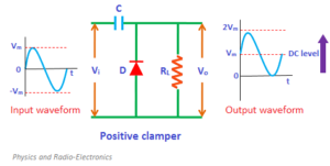
What is a Clamper? Clamping Circuit provides an important role in output waveform and is used to shift either the positive or negative peaks of the input signals to a required level. This clamping circuit can be used as negative or positive which depends on the diode configuration. this circuit is also called a level shifter or DC restorer.

Here clamper circuits classified into two types they are,

  • Positive Clamper circuit
  • Negative clamper Circuit

Positive Clamper Circuit

positive clamper circuit

Positive Clamping Circuit that changes the DC level of a signal to the desired level without changing the shape of the applied signal. If the circuit pushes the signal upwards then the circuit is called a positive clamper. When the signal is pushed upwards, the negative peak of the signal gets the zero level.

Negative Clamper Circuit

negative clamper Circuit

A negative Clamping Circuit opposite of a positive clamper, if the circuit pushes the signal downwards then the circuit is said to be a negative clamper. When the signal is pushed downwards, the positive peak of the signal meets the zero level.

These clamping circuits can be positive or negative depending on the diode configuration

Also Read: What is Clamper Circuit?


Friday, October 15, 2021

Variable Resistor Symbol | Rheostat Symbol & Types of Variable Resistors and Applications

What is a Variable resistor:

A Variable resistor is a type of resistor in which the electric flow of current can be controlled by adjusting the resistance value. This variable resistor works the same as a normal resistor at a fixed value and if the resistance value increases in the variable resistor the current through the circuit decreases and if the resistance value decreases the current flow through the variable resistor increases. It is also used as voltage-controlled across devices in a circuit. The variable resistor must operate by sliding the contact (wiper) onto the electromechanical transducer and usually on the resistive element.

Variable Resistor Symbol:

variable resistor symbol


Types of variable resistors:

Potentiometer:

The potentiometer is a type of resistor and is a three-terminal resistor with a rotating contact. It functions as a potential divider If only two terminals are used, one end and the wiper, it acts as a variable resistor or rheostat. The principle of a potentiometer is that the potential dropped across a segment of a wire of uniform cross-section carrying a constant current is directly proportional to its length.

Potentiometer symbol

Resistor:

A resistor is an electrical component that resists the flow of electric current. It is used to control the amount of current flowing in a circuit, as well as to adjust the voltage level in a circuit. Resistors are typically made from materials such as carbon or metal, and their resistance is measured in ohms. They are widely used in electronic circuits to perform a variety of functions, including voltage division, current limiting, and power dissipation. They come in various types and shapes, such as fixed resistors, variable resistors, wire-wound resistors, and surface-mount resistors. The most common type is the carbon composition resistor, which is a simple and inexpensive option.

Applications of Potentiometers:

Potentiometers are commonly used to control electrical devices

  1. Volume controls in Audio Circuits.
  2. Potentiometers can be used as position mechanism transducers.
  3. Potentiometers are used in Joysticks.
  4. Variable Resistors are measurements of the distance or angles, tuning of the circuits, and many more.
  5. Potentiometers are used as amplifier gain control.
  6. The potentiometer is used as a voltage divider in the electronic circuit.
  7. The potentiometer is used in medical equipment.
  8. The potentiometer is used in radio and television (TV) receivers for volume control.

Potentiometer Symbol:

potentiometer Symbol circuits99

Rheostat:

A Rheostat is a type of resistor the most common way to vary the resistance in a circuit continuously is to use a rheostat. The adjustable resistor is used in applications that require the adjustment of current or the varying resistance in an electric circuit. Rheostats are much related to the potentiometers in terms of construction, but they are not used as a potential divider, instead, they are used as variable resistors. The resistive wire is wound around an insulating ceramic core and the wiper slides over the windings

Rheostat circuit

Rheostat Applications:

  1. Rheostats are used in dim lights to change the intensity of light.
  2. It is basically used to adjust the magnitude of current in a circuit by changing length.
  3. Rheostats are used as the power controlling devices, which were connected in series with the load.
  4. Used in high-efficiency switching electronics.
  5. which are used in circuits to perform tuning or calibration.

Rheostat Symbol:

Rheostat Symbol


Variable Resistor Applications:

Variable resistors are widely used in a variety of electronic applications, including:

  1. Volume controls in audio equipment: Variable resistors are used to adjust the volume of music or speech.
  2. Light dimmers: Variable resistors are used to control the brightness of lights in homes and buildings.
  3. Motor speed control: Variable resistors are used to adjust the speed of electric motors in appliances and machinery.
  4. Temperature control: Variable resistors are used to control the temperature in heating and cooling systems.
  5. Potentiometers: Variable resistors are also used as potentiometers, which are devices that measure the electrical potential (voltage) in a circuit.
  6. Sensors: Variable resistors are used as sensors for measuring position, pressure, and other variables.
  7. Power control: Variable resistors are also used in power control circuits to adjust the amount of power delivered to a load.
  8. Filtering: Variable resistors are also used in filtering circuits to adjust the cutoff frequency of a filter.


Sunday, October 10, 2021

Ceiling Fan Connection Diagram | Uses of Capacitor for Fan & Fan Condenser

What is the Role of Capacitor for Fan

The Capacitor for Fan plays a major role in ceiling fan, capacitors used not only for start the fan but also to make it runs. Normally ceiling fan don’t have rotating magnetic field why because it is single phase motor type but it has two windings which are starting winding and running winding. Capacitors creates leading angle between the two windings and hence rotating magnetic field produced in it.

Fan Capacitor images

Fan Capacitor

In this article we will discuss about Ceiling Fan Connection, Fan Condenser working and  Fan wiring, normally ceiling fan is nothing but single phase induction motor. This motor working same like induction motor according to construction.

Also Read: Parallel Plate Capacitor | Parallel Plate Capacitance with Dielectric

Ceiling Fan Connection with Capacitor Diagram

Ceiling Fan consists of two windings inside motor namely Starting winding and Running winding. Here Starting winding also called as Auxiliary winding and Running winding also Called as Main winding.

Ceiling Fan Connection diagram


Ceiling Fan Connection Diagram

From the above circuit diagram capacitor plays an important role in ceiling fan which are connected in series with the starting winding (Auxiliary winding). This capacitor and starting winding combination is connected parallel to the running winding (Main winding). By connecting the capacitor for the starting winding to produced two phase which is called split phase and produce rotational magnetic field in the stator. Ceiling Fan without Capacitor cannot self start motor itself that is why capacitor must be used in single phase motors.

Fan Condenser Uses

Fan condensers is nothing but Capacitors and some times call it as condensers in practical manner and they uses are:

  1. The capacitor is used not only to start the fan but also to make it spin.
  2. Fan Capacitors are widely used for their reliability and consistent performance.
  3. To generate a revolving magnetic field.
  4. Fan condenser makes 90 degrees leading angle.

Generally the rating of Fan Condensers are 2.5μF to 3.5μF this capacitors are used as permanently in motor which motors are called capacitor start and capacitor run motors.

Read Also: AC to DC Converter Circuit | 220v to 12v dc converter circuit diagram


Thursday, October 7, 2021

50W MOSFET Amplifier Circuit diagram | IRF530 MOSFET Datasheet Pdf Download

50 Watts MOSFET Amplifier

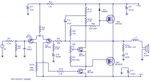
50-watt power MOSFET Amplifier operates on +35V to -35V  range, the input voltage is pre-filtered and pre-amplified before applying to the MOSFET switch. This general audio amplifier is MOSFET, Except for the output power MOSFET, instead, we use J49 and K134, which are more expensive than necessary, We use dual output number J162/K1058, which is Cheap much more.


MOSFET amplifier

50 Watts MOSFET Amplifier Circuit diagram.

MOSFET Characteristics

  • MOSFETs are having 3 terminal 
  • MOSFETs are Unipolar
  • It has a high input impedance 
  • MOSFETs are used as a voltage-controlled device
  • MOSFET behaves like an open switch

MOSFET Applications

  • MOSFETs are generally used in automotive electronics.
  • used as switching devices in electronic control units.
  • used as power converters in modern electric vehicles.
  • The insulated-gate bipolar transistor (IGBT).
  • A hybrid MOS-bipolar transistor is also used for a wide variety of applications.

MOSFETs Can be used like any linear amplifier. They must be polarized so that the majority of current carriers flow from source to drain. The gate-source capacitor is biased, which means that the transistor acts in the middle between cut-off and saturation like all-transistor amplifiers.

IRF530 MOSFET Datasheet Pdf Download

Read Also: 100W MOSFET POWER AMPLIFIER CIRCUIT DIAGRAM

Wednesday, October 6, 2021

Potentiometer Types | Types of Potentiometers | Potentiometer Symbol

What is a Potentiometer?

In this article explains Potentiometer types and its having a 3-terminal device, it is manually adjustable variable resistor. This potentiometer commonly named as a potmeter or pot, the two terminals of the potentiometer connected to opposite ends that is resistive element and the 3rd terminal used as sliding contact which is movable it is called a wiper and moving upside of resistive element. The potentiometer essentially acting as a variable resistance divider. let us suppose two resistors connected in series, where the wiper place identify the resistance ratio of the first resistor to the second resistor.

potentiometer symbol

Potentiometer Symbol

Potentiometers are commonly used for control the electrical and electronic devices like in audio equipment used as volume controls. Potentiometers operating like position transducers, for example joystick. Potentiometers power consumption is more than a watt so rarely used as direct control of power.

Types of Potentiometers

potentiometers types are:

  • Rotary potentiometers
  • Linear potentiometers

Rotary Potentiometers

Rotary type Potentiometers most widely used for providing variable supply voltage in both electrical circuits and electrical circuits. The best example for rotary potentiometer for volume controller of a transistor radio where the rotary knob of the potentiometer which controls the supply to the amplifier.

Rotary potentiometer having two terminals which is semi circular pattern a uniform resistance is placed and the middle terminal which is connected to resistance through a sliding contact.By rotating the knob one can move the sliding contact on the semi-circular resistance. The voltage is taken between a resistance end contact and the sliding contact.

Linear Potentiometers

linear potentiometer

This type of Linear potentiometers is mainly used to measuring in internal resistance of a battery cell and also measure the voltage across a branch of a circuit. It is widely used in the equalizer of musical equipment and Audio amplifier mixing systems.

Rheostat

Rheostat is nothing but variable resistor or adjustable resistor used for adjustment of current or voltage varying of resistance in an electric circuit. The applications of rheostat can control the dim lights and speed of motors and also adjust the generator characteristics.

Rheostat images

Digital potentiometers

A digital potentiometer is nothing but digital resistor but same action as normal potentiometer but in place of mechanical action. Digital potentiometers used in digital signals and switches, but resistance varying by digital process. This is frequently done by making the use of a string of small resistors connected in series.

Digital potentiometer

Potentiometer Symbols


Applications of Potentiometer

Many different applications of potentiometers are,

  • Comparing the EMF of a battery cell with a standard cell
  • Measuring the internal resistance of a battery cell
  • Measuring the voltage across a branch of a circuit

write on :  potentiometer pinout,potentiometer wiring,variable resistor

Tuesday, October 5, 2021

Voltage Booster Circuit Diagram & Applications | DC to DC Boost Converter

Voltage Booster Circuit

Basically, a Simple Voltage Booster Circuit is also DC-DC Converter or booster. These are comes under electronic circuits it can be either step up or step down the DC Voltage to get the required voltage level. Actually these DC voltage booster circuit it can boosts a low DC voltage to high DC voltage, namely 1.5V to 3V to desired higher DC levels of DC to DC Boost Converter

In many industrial applications and required to convert fixed DC voltage supply into variable voltage DC supply also by using voltage booster circuit. This is simple voltage booster circuit by using lesser components, this circuit can boost the battery voltage from 1.5V to 40V to 70V DC. We already discussed above it is DC to DC step up converter, but the output current of circuit low is around 20mA when the step up condition. This circuit helps where we required in which a high voltage and low current applications.

Read also: DC to DC converter +12V to +/-20V Circuit

Simple Voltage Booster Circuit Diagram


Simple Voltage Booster Circuit

Voltage Booster Circuit Diagram

From the above circuit, the output of the voltage booster circuit on the inductive coil used. Suppose if we use 220uH coil is used, the max output of the circuit can be around 40V DC. Similarly, 470uH coil can gets up to 70v DC vice versa.

Finally, the desired output voltage can be achieved by Zener diode. For example if we want to 24v DC voltage then you can use a 24V Zener Diode.

The above circuit is made by using two transistors that are 2N3904 and 2N3906. The coil used in the circuit is fixed coil the purpose of the coil for getting desired voltage. These coils looks same as resistors and can be easily easily purchased at local market. The voltage is increased by increasing the coil value and desired output can be produced by Zener Diode Value.

Components for Voltage Booster Circuit

  • 1.5V AA Battery
  • Resistors – 220k, 100k, 1K.
  • Transistors – 2N3904, 2N3906
  • Diode – 1N4148
  • Zener Diode

Simple Voltage Booster Applications

  • Used in Automotive applications.
  • Power amplifier applications.
  • Adaptive control applications.
  • Battery power systems.
  • Used in Consumer Electronics.
  • Communication Applications.

Read also: AC to DC Converter Circuit | 220v to 12v dc converter circuit diagram


Sunday, October 3, 2021

12v to 5v DC-DC Converter Circuit Diagram | 12V to 5V Converter using 7805 IC

12V to 5V converter

In this article I would like to explain about 12v to 5v Converter which is DC-DC step down type converter. If you want to 5V DC power supply for making digital circuits like audio pre amp circuits, Dolby and optical circuits, Arduino boards mostly required. But in this case if you have only 12v power supply then you need to convert 5v by DC-DC converter for reducing power supply.

In most of digital circuits required 5V DC power supply, but we have only 12V power supply or Battery source then if you want to 5V DC power supply in that case you require 12V to 5V converter it is also known as DC-DC converter or step down regulator.

Here many ways we have, it depends on circuits you are used and other is suitability of components used. 12V to 5V power supply converted by using 7805 voltage regulator circuit.

Read also: 24V, 2A Power Supply Circuit for 30w Power Amplifier

What is LM7805 Voltage Regulator

LM7805 is a voltage regulator, it gives output 5 Volts like same as other regulators in the market. which is a 3- terminal regulator they are input, middle pin is ground and other is output. It has internal thermal- overload protection, this regulator gives output is +5v with current up to 1.5A. You can easily identify the IC 7805 voltage rating by its number like the last two digits of the IC. Example: LM7805 is gives output voltage 5V.

7805 Voltage Regulator PIN Diagram

7805 voltage regulator


7805 PIN Out

12v to 5v DC-DC Converter Circuit Diagram

12v to 5v converter circuit

12V to 5V Converter Circuit

This 12V to 5V DC-DC Converter circuits making is simple by using 7805 IC and together with some other components. It is simple circuit, from above circuit shows all the parts needed for a making voltage regulator to work properly. This 12V to 5V Converter using 7805 for getting constant voltage applications in digital circuits.

This 7805 voltage regulator circuit requires 470µF capacitor keep at input side and 1µF capacitor near the output of 7805 IC. In this circuit Vin is the unregulated DC source or battery source taken through Diode 1N4007. Vout is regulated 5V DC output of 7805IC.

LM7805 Features

  • It has 3-terminal regulator.
  • It has power-dissipation capability.
  • Internal short-circuit current limiting.
  • Output current gives up to 1.5A.
  • Internal thermal-overload protection.
  • Absolute maximum input voltage 35V.
  • Recommended opening condition are minimum input voltage 7V and maximum 25V.

LM7805 Applications

LM7805 is used in many circuits they are,

  • It is used as fixed-output voltage regulator.
  • Variable output regulator.
  • Used as current regulator.
  • Reverse bias projection circuit.

Read Also: AC to DC Converter Circuit | 220v to 12v dc converter circuit diagram

IR Sensor Module Working with Arduino

IR Sensor Module Working Introduction Introduction : Start with a brief introduction to the IR Sensor Module and its applications. Mention t...