Saturday, November 20, 2021

What is a Power Amplifier? | Types of Power Amplifiers, Amplifier Price

What is a Power Amplifier?

In this article, we will discover an interesting subject in the field of electronics the power amplifier. They are used in Audio applications, Radio communications, Medical equipment like MRI, headphones, RF transmitters, and more. Thus, we will learn what the power amplifier is, what are the different types of power amplifiers, the classes of power amplifiers, and also some applications.

Power Amplifier

Power Amplifiers are basically used to increase the power level of the input signal. A power amplifier, also known as a large signal amplifier, needs to have a high input signal voltage to get high power at the output.

Types of Power Amplifiers

Power Amplifiers are divided into the following three types they are Depending on the type of output device connected

  • Audio Power Amplifiers
  • RF Power Amplifiers
  • DC Power Amplifiers

Audio Power Amplifiers

An audio power amplifier (or power amplifier) is an electronic amplifier that amplifies low-power electronic audio signals such as a signal from a radio receiver or an electric guitar microphone to power speakers or earphones.

RF Power Amplifiers

Radio Frequency power amplifier (RF power amplifier) is a type of electronic amplifier that converts a low-power radio frequency signal into a high power signal. Typically, RF power amplifiers drive the transmitter antenna. Design goals often include gain, output power, bandwidth, power efficiency, low linear signal compression at rated output, matching input and output impedance, and heat dissipation…

DC Power Amplifiers

A Direct-Coupled Power amplifier, or DC Power Amplifier, is a type of amplifier that combines the output of one phase of the amplifier with the input of the next phase to enable zero frequency signals, also known as direct current. , Go from the entrance to exit.

Applications of Power Amplifiers

  • Power amplifiers are most widely used in broadcast transmitters,
  • Used in wireless transmitters and high audio systems.
  • Bipolar transistors are used for these applications.
  • Power output and efficiency are mostly considered in power amplification.
  • Industrial Applications like Switching type power amplifiers are used for controlling the industrial actuator systems like Servo motors and DC motors.
  • Audio power amplifiers are used in almost all consumer electronic devices ranging from microwave ovens, headphone drivers, televisions, and Home theatre systems.

Wednesday, November 17, 2021

SCR Applications | What is SCR (Silicon Controlled Rectifier)

What is SCR?

The term SCR stands for silicon-controlled rectifier which is one of the most important members of the thyristor family. A silicon-controlled rectifier or semiconductor-controlled rectifier is a four-layer solid-state current-controlling device.

SCR Applications

SCR Symbol

The silicon-controlled rectifier is a one-way current control device. Like a simple p-n junction diode, it allows current to flow in one direction only and prevents current from flowing in another direction. A common p-n junction diode is made of two semiconductor layers, P-type and N-type. However, an SCR diode is made of 4 semiconductor layers with alternating P and N-type materials.

SCR Applications

Below are some important applications of Silicon Controlled Rectifier (SCR)

  • The silicon-controlled rectifier (SCR) is used in AC voltage stabilizers.
  • The silicon-controlled rectifier (SCR) is used as a switch.
  • It is used in choppers.
  • The silicon-controlled rectifier (SCR) is used in inverters.
  • The silicon-controlled rectifier (SCR) is used for power control.
  • It is used for DC circuit breakers.
  • A silicon control rectifier (SCR) is used in a battery charger.
  • It is used to Adjust the light dimmer.
  • It is used to control motors speed.
  • The SCR is used in the pulse circuits.
  • It is used for AC power control with a solid relay.

SCR Full Form

SCR full form – silicon-controlled rectifier

SCR full form in Electronics

Silicon Controlled Rectifier or Semiconductor Controlled Rectifier

SCR full form in Electrical

Silicon Controlled Rectifier or just Thyristor

Types of Thyristors

  • Silicon controlled thyristor or SCRs
  • Gate turn off thyristors or GTOs
  • Emitter turn off thyristors or ETOs
  • Reverse conducting thyristors or RCTs
  • Bidirectional Triode Thyristors or TRIACs
  • MOS turn off thyristors or MTOs
  • Bidirectional phase controlled thyristors or BCTs
  • Fast switching thyristors or SCRs
  • Light-activated silicon controlled rectifiers or LASCRs
  • FET controlled thyristors or FET-CTHs
  • Integrated gate commutated Thyristors or IGCTs

Silicon controlled thyristor or SCRs

Silicon-controlled rectifiers or SCRs are used primarily in power applications. An SCR is a semiconductor device that conducts electric current when activated, and blocks current when deactivated. The on and off states of an SCR are controlled by the presence or absence of a controlled current through its gate, which is a control wire in the semiconductor. The majority of SCRs use a thyristor as a control element, though some use an SCR alone.

Gate turn off thyristors or GTOs

Gate turn-off thyristors or GTOs are used to control the flow of a gate device. They are usually controlled by a digital signal which is sent to the gate turn-on thyristors or GTOs. The thyristors or GTOs act like a switch, turning the flow of current off when the signal is high and on when the signal is low. The signal can be set up to turn on multiple thyristors or GTOs in parallel to control the flow of a larger current.

Sunday, November 14, 2021

What is Cricut Machine? & Best Cricut Machines in 2021

Cricut Machine

If you are new to the Cricut machine, you may be surprised what a Cricut machine is? and what does do it exactly? Do we need this machine?

What Is Cricut Machine

Cricut machine images

Actually, a Cricut is a digital die-cutting machine we can able to cut different materials by using this Cricut machine for you to use in an Abundant of craft projects. We can cut materials like paper and vinyl by using the correct cutting blades. Some Cricut Machines also cut fabrics, leather, balsa, and cork.

Best Cricut Machines in 2021

The Best Cricut machine is a great investment for crafters to make desired to cut on paper and vinyl material. In this article, you will get info on many different types of Cricut machines rated by hundreds of users.

The best Cricut Machines are,

Cricut Maker

This best overall product and it comes with a bunch of features that are noticeably absent in other Cricut machines.

  • Cuts 300+ materials
  • 10X more power than other models
  • Works with 12+ tools for pro-level scoring, engraving, debossing & other effects
  • Comes with hundreds of digital sewing patterns
  • Powerful blades
  • Has Bluetooth connectivity
  • Automatically detects whether you are using the right blade or not
  • Produces high-quality cuts very quickly

Cricut Explore Air 2

This feature makes the Explore Air 2 the best Cricut machine for vinyl. Using its embedded Bluetooth technology allows for wireless cutting; only one of its awesome features.

  • Cuts 100+ types of material
  • 2X faster cutting and writing
  • Comes with embedded Bluetooth
  • Comes with free access to Cricut’s design software
  • Ample storage space
  • Precise cutting
  • Offers good value for money

Cricut Joy

It is the most compact cutting machine so far and Cricut Joy allows you to customize your designs using a wide variety of line weights and pen types. The write, doodle, and draw functions can achieve any shapes, patterns, letters, numbers, objects, and more.

  • Super compact, lightweight only 3.9 lbs
  • Cuts 50+ types of material
  • Cuts up to 20-ft long and 4-in wide
  • Card mat for quick custom card
  • Fast and quiet operation
  • Easy to set up, super portable, and easy to travel with
  • 50 free online projects for inspiration

Cricut Easy Press 2

This Cricut Press 2 machine provides both actions like Cricut machine and immersive iron on the machine also,

  • Best for iron-on vinyl
  • Allows for precise temperature control
  • Provides results in at most 60 seconds
  • Light and portable
  • Light and portable
  • Compatible with most heat-transfer vinyl brands
  • Comes in a variety of sizes
  • Gives professional results

Cricut Mug Press

It is a single-button, foolproof mug pressing machine that automates the entire process you don’t have to worry about any setting, Imagine a fancy device that huffs and puffs and transforms your mugs into gorgeous looking personalized drinking companions.

  • Best for printing on 11-16 oz mugs
  • Optimized for Infusible Ink products
  • Safety-conscious and compact design
  • Easy to set up and use
  • Easy setup and operation
  • Infusible Ink technology ensures the designs are permanent
  • The foolproof mechanism that can be mastered by anyone
  • Quick sublimation process
  • No heat or pressure settings required

These are the best cutting machines from Cricut Machines.

Also Read: 5.1 Prologic Board price | B-Tech Audio DTS Boards with Remote Kit With Display

Sunday, November 7, 2021

2000W Power Amplifier Circuit Diagram | Class H Amplifier Circuit Diagram

2000W Power Amplifier

2000W  Power Amplifier Circuit Diagram is the article on circuits99.com explaining 2000W Class AB Power Amplifier Circuit Diagram This is the circuit diagram of 2000W class AB power amplifier.

2000W-Power-Amplifier


2000W Class AB Power Amplifier Circuit Diagram

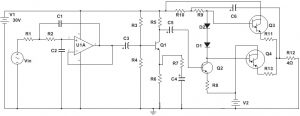
The circuit diagram of the 2000W class AB power amplifier uses 7 pairs of MJ15003 and MJ15004 transistors for the final amplification block. The circuit operated with 90V DC symmetrical (dual polarity) power supply circuit. The transistors must be mounted on the heatsink to prevent overheating, maintain the transistor’s work in maximum performance.

Also Read: 18W AUDIO POWER AMPLIFIER CIRCUIT USING TRANSISTORS

2000W Power Amplifier Specifications:

  • Max. Output Peak Power: 2000 Watt Peak @ 2? Ohms Loudspeaker
  • Max. RMS Output RMS Power: 1000 Watt RMS @ 2? Ohms Loudspeaker
  • Max. Bridged RMS Output Power: 2000 Watt RMS @ 4? Ohms Loudspeaker
  • RMS Output Magnitude: 44.7v RMS
  • Peak Output Magnitude: 65v Peak
  • Freq. Response: 20Hz ~ 20KHz
  • Max. Output Gain: 40dB
  • Input: 100mV Peak
  • DC Power Supply: 90v DC (Dual Supply)

2000 watts power amplifier circuit Working:

  1. This is the circuit diagram of the 2000W class AB power amplifier that uses 7 pairs of MJ15003 and MJ15004 transistors for the final amplification block.
  2. The circuit operated with 90V DC symmetrical (dual polarity) power supply circuit.
  3. The transistors must be mounted on a heatsink to prevent overheating, maintain the transistors’ work in maximum performance.

2000 watt Amplifier Price

Ahuja 2000 watt Amplifier Price

Related:

SUBWOOFER AMPLIFIER CIRCUIT BY IC TDA2030

5.1 Prologic Board price | B-Tech Audio DTS Boards

2000W Class H Amplifier Circuit Diagram

Saturday, November 6, 2021

Fuse Resistor Applications | Fuse Resistor Color Code

What is Fuse Resistor?

Fuse Resistors are used to protect circuits from overheating, voltage spikes, and lightning. They are typically made from a semiconductor material such as a resistive wire or a metal strip and are used in series with other components to reduce the risk of short-circuiting. Fuse Resistors have a resistance that decreases as they warm up. When they reach a certain temperature, the Fuse Resistors turn off, preventing the current from flowing through them.

Wirewound Fuse Resistors

Wirewound Fuse Resistors

Wirewound Fuse Resistor

Wirewound Fuse Resistors are designed to function as a normal resistor under normal conditions and as a fuse at high loads. In the WWF series, resistors up to 5W are color-coded with a resistance value of 3 bands as well as a tolerance band. An additional white stripe indicates that the resistor is fusible. For resistors 6W and above, the value is printed on the resistor.

Which resistor is used for the fuse?

Fusible Film Resistors are used in a variety of low power and low surge applications. These include low-level fire safety, surveillance and maintenance, high-end audio/video systems, environmental management systems and controls, and laser printers.

Applications of Fuse Resistor

  1. Overload or surge production
  2. Low-level fire safety
  3. Used in laser printers

Fuse Resistor Color Code

Queen Mao resistors color-coding system is applicable to carbon films, metal films, metal oxide films, fusible and coiled axial wires. This system is used for resistors when the area is large enough to print the last resistance value.

fuse resistor color code

fuse resistor color-code

Currently, Queen Mao’s resistance color-coding system requires automation. The first three bands closest to one end of the resistance are used to determine the resistance. The fourth band indicates the resistance tolerance. Additional information can be obtained from the first band.

Usually, if the additional fifth band is black, the resistor is a wireless resistor. If the fifth additional band is white, the resistor is a fusible resistor. If there is only one black band in the center, the resistance is called the zero-ohm resistance. The colors of the first two bands indicate the numerical value of the resistance. The third band represents the power-off multiplier -10.

Friday, November 5, 2021

100W Subwoofer Amplifier & Applications

100W Subwoofer Amplifier Circuit

Audio Signal is first filtered to remove the high-frequency signals and allow only the low-frequency signals to pass through it. This low-frequency signal is then amplified using a voltage amplifier.  This low power signal is then 100W Subwoofer Amplifier using a transistor-driven class AB power amplifier.
100W Subwoofer Amplifier

100W Subwoofer Amplifier

Applications of Subwoofer Amplifier Circuit:

  1. This circuit can be used at home theatre systems to drive subwoofers to produce high-quality, high bass music.
  2. This circuit can also be used as a power amplifier for low-frequency signals.

Limitations of the Circuit:

  1. The filter circuit tends to increase the DC level of the audio signal, causing a disruption in the biasing.
  2. The use of linear devices causes power dissipation, thus reducing the efficiency of the circuit.
  3. It is a theoretical circuit and the output contains distortion.
  4. The circuit doesn’t provide any provision to remove the noise signal and thus the output may contain the noisy disturbance.

Purchase Links:

HD Audio Rush DTS / AC3 5.1 Channel https://amzn.to/3gNHGrS

B-TECH Audio BASS Treble and Tone Control Board. https://amzn.to/3oK80HJ

B-Tech Audio 5.1 Prologic Board. https://amzn.to/362TSTh

Audio Amplifier Cabinet. https://amzn.to/3gJIWfB

Tuesday, November 2, 2021

LM317 Voltage Regulator | 24v Lead Acid Battery Charge Controller Circuit Diagram

LM317 Voltage Regulator

LM317 Voltage Regulator: The LM317 device is a three-terminal adjustable positive voltage regulator that can supply more than 1.5A in the output voltage range of 1.25V to 37V. It only needs two external resistors to adjust. the output voltage. The device has normal line control of 0.01% and normal load control of 0.1%. It includes current limit, thermal overload protection, and safe operation zone protection. The overload protection remains active even if the ADJUST terminal is disconnected.

The LM317 voltage regulator is a popular regulator that can be used to adjust the voltage in circuits. The basic LM317 is a versatile regulator that can be used to adjust the voltage in circuits. However, more advanced versions of the LM317 can be used to generate a specific voltage or current or provide a constant current regardless of the input voltage. The LM317 is a surprisingly versatile circuit and can be used in a wide range of circuits and devices.

24v lead acid battery charger circuit diagram

The 24V lead acid battery charger circuit given here is a current limited lead acid battery charger built around the famous variable voltage regulator IC LM317. The charging current depends on the value of resistor R2 and here it is set to be 700mA. Resistor R3 and POT R4 determine the charging voltage.


24v lead acid battery charger circuit diagram

LM317 24v lead acid battery charger circuit diagram

Transformer T1 steps down the mains voltage and bridge D1 does the job of rectification. C1 is the filter capacitor. Diode D1 prevents the reverse flow of current from the battery when the charger is switched OFF or when mains power is not available.

Discover the best 12V Batteries in Best Sellers online on amazon

LM317 Voltage Regulator Circuit Making

Assemble the circuit on a good quality PCB.
T1 can be a 230V primary, 35V/3A secondary step-down transformer.
If 3A Bridge is not available, make one using four 1N5003 diodes.
LM317 must be fitted with a heat sink.
R2 = 0.85 ohm is not a standard value. You can obtain it by combining 6.2 ohm and 1-ohm resistors in parallel.
F1 can be a 2A fuse.
To set up the charging voltage, power ON the charger hook up a voltmeter across the output terminals and adjust R4 to make the voltmeter read 28V. Now the charger is ready you can connect the batteries.
This charger is specifically designed for two 12V/7AH/6 cell lead-acid batteries in series OR a 24V/7AH/12 cell lead-acid battery.

LM317 Pinout

LM317 Pinout

LM317 Pinout Diagram

The LM317 Voltage Regulator is a 3-terminal adjustable voltage regulator which can supply an output voltage adjustable from 1.2V to 37V. It can supply more than 1.5A of load current to a load.

LM317 Voltage Regulator Schematic Diagram

LM317 Voltage Regulator schematic diagram

LM317 Schematic Diagram

LM317 Features

  1. Output voltage range adjustable from 1.25 V to 37 V.
  2. Output current greater than 1.5 A.
  3. Internal short-circuit current limiting.
  4. Thermal overload protection.
  5. Output safe-area compensation.

Lm317 IC Applications

  1. ATCA solutions.
  2. DLP: 3D biometrics, hyperspectral imaging, optical networking, and spectroscopy
  3. Desktop PCs
  4. Digital signage and still cameras
  5. ECG electrocardiograms •
  6. EV HEV chargers: levels 1, 2, and 3
  7. Electronic shelf labels
  8. Energy harvesting
  9. Ethernet switches
  10. Femto base stations
  11. Fingerprint and iris biometrics
  12. HVAC: heating, ventilating, and air conditioning
  13. High-speed data acquisition and generation •
  14. Hydraulic valves.

LM317 Datasheet Pdf

Here you can download the LM317 Datasheet pdf and I keep the copy and paste the link given below

https://www.ti.com/lit/ds/symlink/lm317.pdf?ts=1635903282835&ref_url=https%253A%252F%252Fwww.google.co.id%252F

Monday, November 1, 2021

8051 microcontroller Projects based Heart Rate Monitor HRM with SMS Alert

Heart Rate Monitor HRM with SMS Alert

This project is 8051 microcontroller Projects based Heart Rate Monitor HRM with SMS Alert. Heart rate is sensed from the fingertip using a phototransistor / IR LED pair. This method is called photoplethysmography. Photoplethysmography is the volumetric assessment of an organ/tissue using light. IR reflection photoplethysmography is the exact method used here.


Heart Rate Monitor HRM with SMS Alert

Heart Rate Monitor HRM with SMS Alert Circuit

In this Heart Rate Monitor HRM with SMS Alert, IR waves are sent to the tissue, and reflected wave is picked using a photo-transistor. When the heart beats the volume of blood will be more in the tissue. This time more light gets reflected onto the phototransistor. When the heart is not beating the volume of blood inside the tissue will be less and so less light gets reflected onto the photo-transistor. The result will be a pulse waveform at the collector of the photo-transistor. The rate of this pulse waveform will be equal to the heart rate. The waveform is amplified, filtered, squared, and fed to the microcontroller for counting. The circuit diagram of this heart rate monitor is shown below.

heart rate monitor using 8051 microcontroller project report

The GSM module is interfacing with the 8051 microcontrollers using serial communication. RX pin of the GSM module is connected to the TX pin of the microcontroller. A relay is connected to P2.0 through a driving transistor. This relay can be used to switch an alarm or any other device when the heart rate goes above 80 beats per minute. The heart rate is also displayed on a 16×2 LCD module. The LCD module is interfaced through Port 0 and Port 2 of the microcontroller. S2 is a reset switch

Program for Heart Rate Monitor HRM with SMS Alert

 RS EQU P2.7    RW EQU P2.6    E  EQU P2.5    ORG 000H  MOV DPTR,#LUT              MOV P2,#00000000B          MOV P0,#00000000B         ACALL INITACALL TEXT1 ACALL LINE2ACALL TEXT3         MAIN: MOV R6,#228D      SETB P3.5                  MOV TMOD,#01100001B        MOV TL1,#00000000B        MOV TH1,#00000000B         SETB TR1           BACK: MOV TH0,#00000000B         MOV TL0,#00000000B         SETB TR0             HERE: JNB TF0,HERE               CLR TR0                   CLR TF0                   DJNZ R6,BACK      CLR TR1                    CLR TF0                    CLR TF1                   MOV A,TL1      MOV B,#4D      MUL AB      MOV R7,A      CJNE A,#80D,SKIP SKIP: JC SKIP1      SETB P2.0SKIP1:JNC CONT      CLR P2.0 CONT:CLR PSW.7      ACALL SPLIT       ACALL INIT      ACALL TEXT1      ACALL LINE2      ACALL TEXT2      ACALL BPM       ACALL GSM      SJMP MAIN  GSM:     MOV TMOD,#00100001BMOV TH1,#253DMOV SCON,#50HSETB TR1MOV A,#"A"ACALL SENDMOV A,#"T"ACALL SENDMOV A,#0DHACALL SENDACALL DELAY1MOV A,#"A"ACALL SENDMOV A,#"T"ACALL SENDMOV A,#"+"ACALL SENDMOV A,#"C"ACALL SENDMOV A,#"M"ACALL SENDMOV A,#"G"ACALL SENDMOV A,#"F"ACALL SENDMOV A,#"="ACALL SENDMOV A,#"1"ACALL SENDMOV A,#0DHACALL SENDACALL DELAY1MOV A,#"A"ACALL SENDMOV A,#"T"ACALL SENDMOV A,#"+"ACALL SENDMOV A,#"C"ACALL SENDMOV A,#"M"ACALL SENDMOV A,#"G"ACALL SENDMOV A,#"S"ACALL SENDMOV A,#"="ACALL SENDMOV A,#34DACALL SENDMOV A,#"+"ACALL SENDMOV A,#"9"ACALL SENDMOV A,#"1"ACALL SENDMOV A,#"9"ACALL SENDMOV A,#"8"ACALL SENDMOV A,#"4"ACALL SENDMOV A,#"7"ACALL SENDMOV A,#"2"ACALL SENDMOV A,#"4"ACALL SENDMOV A,#"2"ACALL SENDMOV A,#"9"ACALL SENDMOV A,#"6"ACALL SENDMOV A,#"1"ACALL SENDMOV A,#34DACALL SENDMOV A,#0DHACALL SENDACALL DELAY1MOV A,#"B"ACALL SENDMOV A,#"P"ACALL SENDMOV A,#"M"ACALL SENDMOV A,#"="ACALL SENDMOV A,R1ACALL ASCIIACALL SENDMOV A,R2ACALL ASCIIACALL SENDMOV A,R3ACALL ASCIIACALL SENDACALL DELAY1MOV A,#1AHACALL SENDACALL DELAY1RETSEND:CLR TI     MOV SBUF,AWAIT:JNB TI,WAIT     RETDELAY1:MOV R6,#15D       BACK1: MOV TH0,#00000000B          MOV TL0,#00000000B          SETB TR0             HERE1: JNB TF0,HERE1              CLR TR0                    CLR TF0                   DJNZ R6,BACK1      RET   INIT:     MOV A,#0FH     ACALL CMD    MOV A,#01H     ACALL CMD    MOV A,#06H     ACALL CMD    MOV A,#83H     ACALL CMD    MOV A,#3CH     ACALL CMD    RETTEXT1:    MOV A,#"H"    ACALL DISPLAY    MOV A,#"e"    ACALL DISPLAY    MOV A,#"a"    ACALL DISPLAY    MOV A,#"r"    ACALL DISPLAY    MOV A,#"t"    ACALL DISPLAY    MOV A,#" "    ACALL DISPLAY    MOV A,#"R"    ACALL DISPLAY    MOV A,#"a"    ACALL DISPLAY    MOV A,#"t"    ACALL DISPLAY    MOV A,#"e"    ACALL DISPLAY    RETLINE2:    MOV A,#0C0H     ACALL CMD    RET     TEXT2:       MOV A,#"b"    ACALL DISPLAY    MOV A,#"p"    ACALL DISPLAY    MOV A,#"m"    ACALL DISPLAY    MOV A,#" "    ACALL DISPLAY    RET     TEXT3:    MOV A,#"c"    ACALL DISPLAY    MOV A,#"o"    ACALL DISPLAY    MOV A,#"u"    ACALL DISPLAY    MOV A,#"n"    ACALL DISPLAY    MOV A,#"t"    ACALL DISPLAY    MOV A,#"i"    ACALL DISPLAY    MOV A,#"n"    ACALL DISPLAY    MOV A,#"g"    ACALL DISPLAY    MOV A,#"."    ACALL DISPLAY    MOV A,#"."    ACALL DISPLAY    MOV A,#"."    ACALL DISPLAY    RET  BPM:       MOV A,R1    ACALL ASCII    ACALL DISPLAY    MOV A,R2    ACALL ASCII    ACALL DISPLAY    MOV A,R3    ACALL ASCII    ACALL DISPLAY    RET          CMD: MOV P0,A    CLR RS    CLR RW    SETB E    CLR E    ACALL DELAY    RET DISPLAY:MOV P0,A    SETB RS    CLR RW    SETB E    CLR E    ACALL DELAY    RET DELAY: CLR E    CLR RS    SETB RW    MOV P0,#0FFh    SETB E    MOV A,P0    JB ACC.7,DELAY    CLR E    CLR RW    RET       SPLIT: MOV B,#10D       DIV AB       MOV R3,B       MOV B,#10D       DIV AB       MOV R2,B       MOV R1,A       RET      ASCII: MOVC A,@A+DPTR       RET    LUT: DB  48D     DB  49D     DB  50D     DB  51D     DB  52D     DB  53D     DB  54D     DB  55D     DB  56D     DB  57D       END

IR Sensor Module Working with Arduino

IR Sensor Module Working Introduction Introduction : Start with a brief introduction to the IR Sensor Module and its applications. Mention t...