Sunday, February 26, 2023

4558 IC Subwoofer Bass Booster Circuit diagram | 4558 IC Circuit Diagram, Datasheet Pdf

4558 IC Subwoofer Bass Booster Circuit:

In this article, we’ll learn how to build a circuit using 4558 IC and its applications. We will discuss the pin configuration, working principle, and circuit diagram of 4558 IC.

In this article, I would like to explain this 4558 IC-based Subwoofer bass booster circuit which is used only for BASS sound.

The 4558 IC is an excellent Bass booster and it helps to increase extra bass without any disturbance. This bass booster circuit reduces the audio frequency to a lower value. The actual concept of the bass booster is for low-frequency sounds.

If you want extra bass then you can use this circuit. This circuit doesn’t give a treble sound. This Sub Woofer circuit is only for Bass speakers not for Tweeters.

Read Also: 250W RMS Power Amplifier Legend Stage Master Circuit Diagram

Bass Booster Circuit 

2.1 Preamp Bass Filter Circuit 4558 Opamp

This circuit is used only for Bass, Extra Bass effect will be produced by this Bass Booster circuit, this sound is achieved by using IC 4558.

This Bass Booster gives clear sound without any noise and this can be produced by very low-frequency sound. Low-frequency sound can be produced by a low pass filter circuit, it can block the high-frequency sound.

High-frequency range sounds are treble, as well as low-frequency sounds are Bass. If you want an extra bass effect, then you can make the Bass Booster circuit.

4558 Circuit Diagram

4558 IC

IC 4558  Subwoofer Bass Circuit Diagram

4558 IC PinOut


4558D Pin diagram

4558IC Pinout Diagram

IC 4558 Subwoofer Circuit:

  • Bass Booster Circuit increases BASS for speakers.
  • It Works With Any Amplifier Circuit.
  • Dual Op-Amp IC
  • 4558IC is mainly for Audio Player, Recorder, Amplifier Etc

Read Also: 5.1 Prologic Board price | B-Tech Audio DTS Boards with Remote Kit With Display

4558 IC Datasheet pdf

Download 4558 IC Datasheet Pdf

How To Make Mega Bass Booster Circuit Using 4558

People Asked Questions

What is 4558 IC?

  • 4558 is a Monolithic IC.
  • It is a dual-operational amplifier.

What are the Features of 4558 IC?

Ans: It has a low power consumption of about 50mW, High gain, Short circuit protection, and low noise.

4558 IC Circuit Diagram Applications

  • This 4558 IC can work with any amplifier circuit.
  • 4558D IC Circuit is Dual Op-Amp.
  • 4558 IC mainly used for bass boosters in audio circuits
  • 4558 IC Circuit used for Recorders and Amplifier

Conclusion: The 4558 IC is a dual Schmitt trigger IC, or in layman’s terms, a pair of gated D-type flip-flops. These two devices are to perform binary counting actions

This IC is working as an oscillator, that generates square waves with different frequencies. It’s an essential part if you want to build your own clock circuit or any other timing-related circuit.


4440 IC Amplifier Circuit Diagram | LA4440 IC Datasheet Pdf, 4440 IC Board Price

LA4440 IC Amplifier Circuit

In this article I would like to explain about IC 4440 amplifier circuit,  it is operating on 12 volts but the output is very high and quality. This LA 4440 IC output can be getting 19 watts with 12 volts supply, this amplifier is widely used for car audio players why because this LA 4440 IC amplifier requires a single supply means (0-12v). It is cheap and the best amplifier for good results and also we can use this IC 4440 as stereo and as well as mono. Example: if built-in 2 channels (dual) enable use in stereo 6wx2=12w, and built-in as bridge amplifier output gets 19w. If you want to study this IC then you can check the 4440 IC datasheet pdf given below.

4440 IC

4440 IC Amplifier Circuit Diagram

Working of Circuit:

As you can see above circuit diagram of IC 4440 is a 6w+6w stereo amplifier built around two loudspeakers and some other components like capacitors and resistors. from the above circuit 3 pin connector which is CON2 provides for Input signal (left- ground- right) channels, left channel audio input is connected to pin 6 of IC1 through the capacitor c1 which is 4.7µF/35V, and the right channel input is connected to pin 2 of IC1 through capacitor C2 (4.7µF/35V).

+12V power supply is connected to pin 11 of IC1, and electrolytic capacitor C12 (1000µF/35V) is connected between +12V and ground to act as a filter. In this article, you can find below LA4440 IC Datasheet Pdf

Read Also: 4558 IC Subwoofer Bass Circuit diagram | IC 4558 Specifications and Datasheet Pdf Download

Components Required:

1. LA4440 IC

2. Resistors R1, R2 – 2.2k ohm

3. Capacitors C1, C2 – 4.7µF/35V electrolytic

C3,C7 – 100µF/35V electrolytic

C8,C9 – 220µF/35V electrolytic

C10,C11 – 0.1 µF Ceramic Disk

C12 –  1000µF/35V electrolytic

Features of IC 4440 Amplifier Circuit:

  • Built-in 2 channels (dual) enabling use in stereo and bridge amplifier applications.
    Dual: 6W×2 (typ.)
    Bridge: 19W (typ.)
  • A minimum number of external parts is required.
  • Small pop noise at the time of power supply is ON/OFF and a good starting balance.
  • Good ripple rejection: 46dB
  • Good channel separation.
  • Small residual noise (Rg=0).
  • Low distortion over a wide range from low frequencies to high frequencies.
  • Easy to design radiator fin.
  • Built-in audio muting function.
  • Thermal protector.
  • Overvoltage, surge voltage protector.
  • Pin-to-pin short protector

4440 IC Pinout

4440 ic pinout

LA4440 IC pinout diagram

4440 IC Datasheet Pdf Download

4440 IC Board Price

Voltage12 Volts
ManufacturerRepro
BrandSoumik Electricals
Number of Channels2
  • Power Supply- 12 Volt
  • Awesome for Car
  • Dual-Channel
  • 40 Watt Per Channel

4440 IC Board Wiring Diagram

4440 ic board

4440 IC Board 

Purchase Links:

HD Audio Rush DTS / AC3 5.1 Channel https://amzn.to/3gNHGrS

B-TECH Audio BASS Treble and Tone Control Board. https://amzn.to/3oK80HJ

B-Tech Audio 5.1 Prologic Board. https://amzn.to/362TSTh

Audio Amplifier Cabinet. https://amzn.to/3gJIWfB

4440 IC Board Full Wiring and A to Z Connections Detailed

Do people also ask Questions?

What is the use of 4440 IC?

Ans: This LA4440 IC is a two-channel audio power amplifier, this IC has an inbuilt dual-channel for stereo and bridge amplifier used in the stereo mode it gives an output of 6 watts per channel and in bridge mode, it can deliver 19-watt output.

What is the Output of 4440 IC?

Ans: It gives an output of 19 watts in bridge mode and 6 watts in stereo mode.

What is the 4440 IC Board Price?

Ans: 4440 IC board Price Around Rs.350/- on Flipkart and amazon

Tags: LA4440 IC Datasheet Pdf, what is 4440 IC?, 4440 Ic Output Watts.

Friday, February 24, 2023

What is Oil Circuit Breaker |

Oil Circuit Breaker

An oil circuit breaker (OCB) is a type of circuit breaker that uses oil as the insulating and arc-quenching medium between the contacts. When the circuit breaker is closed, the contacts are immersed in the oil, which acts as an insulator and prevents the current from flowing between them. When the circuit breaker is opened, the contacts are separated, and the resulting arc is quenched by the oil.

Oil circuit breakers were commonly used in high-voltage electrical systems, such as power plants and substations, but they have largely been replaced by newer technologies, such as vacuum circuit breakers and gas-insulated circuit breakers, which offer better performance and are more environmentally friendly. However, some older electrical systems may still use oil circuit breakers.

Oil Circuit Breaker Apllications

Oil circuit breakers (OCBs) were widely used in high-voltage electrical systems before the advent of newer technologies. Some of the applications of oil circuit breakers include:

  1. Power Plants: Oil circuit breakers were commonly used in power plants for high-voltage circuit protection, such as for generator and transformer protection.
  2. Substations: Oil circuit breakers were used in substations to protect the electrical system and prevent damage in the event of an electrical fault.
  3. Industrial Applications: Oil circuit breakers were used in industrial applications where high-voltage circuit protection was required, such as in factories, mines, and refineries.
  4. Railways: Oil circuit breakers were used in railway electrical systems to protect the trains and railway infrastructure.
  5. Marine Applications: Oil circuit breakers were used in marine electrical systems to protect the ship’s electrical system and prevent damage.

It’s worth noting that oil circuit breakers have largely been replaced by newer technologies, such as vacuum circuit breakers and gas-insulated circuit breakers, which offer better performance and are more environmentally friendly.

State Ampere's Circuital Law

State Ampere’s Circuital Law

Ampere’s circuital law states that the line integral of the magnetic field around any closed path is equal to the permeability of free space times the current passing through the enclosed area:

∮ B · dl = μ0 I_enc

where ∮ B · dl is the line integral of the magnetic field B around the closed path, μ0 is the permeability of free space, and I_enc is the total current passing through the area enclosed by the closed path.

This law relates the magnetic field to the current that produces it and is a fundamental principle of electromagnetism. It is applicable to any closed path, whether it is a simple loop or a more complex shape.

What is Ampere’s Circuital Law

Ampere’s circuital law is one of the four Maxwell’s equations, which are a set of fundamental equations describing the behavior of electric and magnetic fields. It was first formulated by André-Marie Ampère in 1826 and was later incorporated into Maxwell’s equations.

The law can be used to calculate the magnetic field generated by a current-carrying wire or a solenoid, as well as to determine the current passing through a closed path by measuring the magnetic field along the path. It is also useful in the design of electromagnetic devices such as transformers and motors.

Features of Ampere’s Circuital Law

One important feature of Ampere’s circuital law is that it only applies to steady-state currents, where the current and magnetic field is constant over time. For time-varying currents, the law must be modified to include additional terms that account for the changing electric field.

In addition, Ampere’s circuital law is closely related to the concept of magnetic flux, which is the amount of magnetic field passing through a surface. By applying the law to a surface enclosing a current-carrying wire, one can derive an expression for the magnetic flux through the surface, which is proportional to the current passing through the wire.

Overall, Ampere’s circuital law is a fundamental principle of electromagnetism that is widely used in many areas of science and engineering.

Ampere Circuital Law Class 12

Ampere’s circuital law is one of the four Maxwell’s equations that describe the relationship between electric currents and magnetic fields. It states that the line integral of the magnetic field around a closed loop is equal to the current passing through the loop multiplied by a constant called the permeability of free space (μ0).

In mathematical terms, Ampere’s circuital law can be expressed as:

∮ B ⋅ dl = μ0 I

where:

  • ∮ denotes the line integral taken around a closed loop
  • B is the magnetic field vector
  • dl is an element of the closed loop
  • I is the current passing through the loop
  • μ0 is the permeability of free space, which has a value of approximately 4π x 10^-7 T m/A.

Ampere’s circuital law can be used to calculate the magnetic field around simple current-carrying geometries such as straight wires, solenoids, and toroids. It is also used in conjunction with other Maxwell’s equations to describe the behavior of electromagnetic waves and to develop the theory of electromagnetism.

Tuesday, February 21, 2023

RCCB Full Form | rccb connection diagram & Types of RCCB's

RCCB Full Form

RCCB stands for Residual Current Circuit Breaker. It is an electrical safety device that is designed to protect against electrical shock caused by earth leakage current. RCCBs detect and interrupt current leakage that occurs when current flows through an unintended path, such as through a person’s body. It can quickly disconnect the power supply to prevent injury or damage.

RCCB Full Form in Hindi

आरसीसीबी का फुल फॉर्म हिंदी में रेसिडुअल करंट सर्किट ब्रेकर होता है अर्थात इसका मुख्य कार्य जब भी कोई फॉल्ट होता है तब बिजली के प्रवाह को रोकने के लिए RCCB का उपयोग किया जाता है। यह सर्किट ब्रेकर के माध्यम से लोगों को बिजली के झटके लगने से बचाया जा सकता है।

RCCB Full Form in Electrical

Here’s some additional information about RCCBs in electrical systems:

An RCCB is an electrical safety device that is designed to protect people from electric shock and prevent electrical fires. It works by detecting any imbalance in the electrical current flowing through a circuit, which could be caused by a fault or a person coming into contact with a live wire. If an imbalance is detected, the RCCB will quickly disconnect the circuit, cutting off the power and preventing any harm.

RCCB Applications

Residual Current Circuit Breakers (RCCBs) is a type of electrical safety device that can quickly disconnect a circuit if it detects a difference in current flow between the live and neutral wires. Here are some common applications of RCCBs:

  1. Residential Buildings: RCCBs are commonly used in homes to protect against electric shock and fire caused by faulty appliances or wiring. They can be installed in the main electrical panel or in individual circuits to provide protection for specific areas or appliances.
  2. Commercial Buildings: RCCBs are used in commercial buildings to protect workers and customers from electrical hazards. They are commonly installed in areas where water is present, such as bathrooms, kitchens, and laundry rooms.
  3. Industrial Applications: RCCBs are widely used in industrial applications, especially where electrical equipment is exposed to moisture or other hazardous conditions. They can protect against electric shock and prevent damage to equipment.
  4. Construction Sites: RCCBs are often used on construction sites to protect workers from electric shock. They can be used to provide protection for temporary power sources or for specific tools and equipment.
  5. Agricultural Applications: RCCBs are commonly used in the agricultural industry to protect against electric shock and fire caused by faulty equipment or wiring. They can be used to provide protection for pumps, motors, and other electrical equipment.

Overall, RCCBs are essential safety devices that can help prevent electric shock and fire in a variety of applications.

Monday, February 20, 2023

2N2222 Datasheet pdf Download | 2N2222A Transistor Pinout

2N2222 Datasheet

2N2222 Transistor

The 2N2222 is a widely used bipolar junction transistor (BJT) that was first introduced by the American company Texas Instruments in the early 1960s. It is a general-purpose NPN transistor that is commonly used in electronic circuits for amplification and switching applications.


2N2222A Transistor


The 2N2222 is a low-power transistor that can handle a maximum current of 600 mA and a maximum voltage of 30 V. Its low noise and high gain make it an ideal choice for applications such as audio amplifiers, radio receivers, and switching circuits.

The 2N2222 is housed in a TO-92 package, which makes it easy to use and compatible with a wide range of breadboards and PCBs. The transistor has three leads, with the collector being the central lead, the emitter being the lead on the left, and the base being the lead on the right.

2N2222A Transistor Pin Configuration


2N2222A Transistor Pin Configuration

  • Pin1 (Collector): This is the first pin of the transistor & it is an o/p pin. The main function of this pin is to provide transistor current toward the o/p load.
  • Pin2 (Base): The base pin is a control pin & it is a second pin of the transistor. The main function of this pin is to control the current from the emitter to the base.
  • Pin3 (Emitter): The emitter pin is the third pin of the transistor & it is used to drain out the complete current of the transistor.

One of the key features of the 2N2222 is its high current gain, which ranges from 75 to 300. This means that a small current applied to the base can control a much larger current flowing through the collector and emitter. This makes the transistor ideal for amplification applications, where small signals need to be boosted to larger levels.

The 2N2222 also has a low saturation voltage, which means that when it is used as a switch, it can turn on and off quickly with minimal power loss. This makes it useful in a range of electronic circuits that require high-speed switching, such as LED drivers and motor control circuits.

In summary, the 2N2222 is a versatile and reliable transistor that has been used in countless electronic circuits over the past six decades. Its high gain, low noise, and low saturation voltage make it a popular choice for amplification and switching applications, and its low cost and ease of use have made it a staple of the electronics industry.

2N2222 Datasheet pdf Download

2N2222A Transistor uses:

The 2N2222A transistor is a popular general-purpose NPN bipolar junction transistor that can be used for a wide range of applications. Some common uses of the 2N2222A transistor include:

  1. Amplification: The 2N2222A can be used as an amplifier to increase the strength of a signal. It is commonly used in audio amplifiers, low-level audio pre-amplifiers, and small signal amplifiers.
  2. Switching: The 2N2222A can also be used as a switch to control the flow of current in a circuit. It is often used in electronic circuits to turn on and off small loads, such as LEDs or small motors.
  3. Oscillation: The 2N2222A can be used as a component in an oscillator circuit to generate a continuous signal. This can be useful in applications such as radio communications or electronic testing equipment.
  4. Voltage regulation: The 2N2222A can also be used as a voltage regulator in certain types of circuits. It can help regulate the voltage in a circuit by shunting current away from the load when the voltage gets too high.

Overall, the 2N2222A is a versatile and widely-used transistor that can be used in many different applications.

2N3904 Datasheet Pdf Download | 2N3904 Transistor Pinout

2N3904 Datasheet

2N3904 NPN Transistor

The 2N3904 is a commonly used NPN bipolar junction transistor (BJT) in electronic circuits. It is widely used as a small signal transistor and can be used for a variety of purposes such as switching and amplification. The transistor has a maximum collector current of 200mA, a maximum collector-emitter voltage of 40V, and a maximum power dissipation of 625mW. It is typically used in digital and analog circuits and is often used as a switch or amplifier in electronic projects.

2N3904 Transistor Pinout

2N3904 Transistor Pinout2N3904 NPN Transistor Pinout

2N3904 Pin Configuration

Pin NumberPin NameDescription
1EmitterCurrent Drains out through the emitter
2BaseControls the biasing of transistor
3CollectorCurrent flows in through the collector

2N3904 Features

  • Bi-Polar NPN Transistor
  • DC Current Gain (hFE) is 300 maximum
  • The continuous Collector current (IC) is 200mA
  • Base- Emitter Voltage (VBE) is 6V
  • Collector-Emitter Voltage (VCE) is 40V
  • Collector-Base Voltage (VCB) is 60V
  • Available in To-92 Package

2N3904 Datasheet pdf Download


Thursday, February 16, 2023

Half Wave Rectifier Diagram | Half Wave Rectifier Working

Half Wave Rectifier

A halfwave rectifier is a type of electronic circuit that converts an alternating current (AC) signal into a pulsating direct current (DC) signal. It works by allowing current to flow through the circuit in only one direction, which results in the elimination of the negative portion of the AC signal.

Half Wave Rectifier Diagram

Half Wave Rectifier Diagram

Half Wave Rectifier Circuit

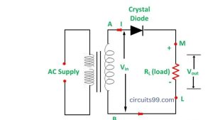
The basic circuit of a half-wave rectifier consists of a diode, a load resistor, and a source of AC signal. The diode is connected in series with the load resistor and is oriented so that current can only flow in one direction, which is determined by the polarity of the AC signal.

Half Wave Rectifier Working

During the positive half cycle of the AC signal, the diode allows current to flow through the circuit and the load resistor, resulting in a positive voltage across the load resistor. During the negative half cycle, however, the diode blocks current flow and there is no voltage across the load resistor.

The output of the half-wave rectifier is a pulsating DC voltage that consists of a series of positive pulses with a period equal to the period of the AC signal. The amplitude of the DC voltage is equal to the peak value of the AC signal minus the forward voltage drop of the diode.

Half-wave rectifiers are commonly used in low-power applications where the efficiency of the circuit is not a critical concern. They are often used in simple power supplies, battery chargers, and voltage regulators.

Half Wave Rectifier Formula

The output voltage of a half-wave rectifier can be calculated using the following formula:

Vout = Vpeak * |sin(ωt)|

Where:

  • Vout is the output voltage
  • Vpeak is the peak value of the input voltage
  • ω is the angular frequency of the input voltage (ω = 2πf, where f is the frequency of the input voltage)
  • t is the time

The absolute value of the sine function is used to ensure that the output voltage is always positive, as the diode in a half-wave rectifier only allows current to flow in one direction

PLC Full Form | What is a PLC?

PLC Full Form

PLC stands for Programmable Logic Controller.

A Programmable Logic Controller (PLC) is a type of industrial control system that is designed to automate processes in manufacturing plants and other industrial environments. PLCs are used to control machinery, monitor production processes, and manage various other aspects of industrial operations.

PLCs consist of a processor, input, and output modules, and programming software. They are programmed using specialized software and can be customized to perform a wide range of functions. PLCs can communicate with other industrial systems, such as sensors and human-machine interfaces, to provide real-time monitoring and control of industrial processes.

What is PLC and how it works?


PLC Full form


PLC stands for “Programmable Logic Controller”. It is a type of digital computer that is used to control and automate industrial processes.

PLCs are designed to be rugged and reliable, able to operate in harsh industrial environments. They are programmed using specialized software, which allows engineers to design and test control logic before it is deployed in the field.

Once programmed, a PLC operates by continually monitoring inputs from sensors and switches in the field, such as temperature sensors, pressure switches, and limit switches. It then executes the control logic programmed by the engineer, which may involve turning on or off motors, valves, or other actuators in response to the sensor inputs.

PLCs can also communicate with other devices, such as human-machine interfaces (HMIs), other PLCs, or even enterprise-level systems, to exchange data and control information. This allows for sophisticated control of complex industrial processes.

Overall, PLCs provide an efficient and flexible means of controlling and automating industrial processes and have become a critical component in many industries, including manufacturing, energy, and transportation.

What are the 3 types of PLC?

There are primarily three types of PLCs, which are:

  1. Modular PLCs: These are the most common type of PLCs and are designed to be customized based on the specific needs of the application. They consist of a rack or chassis that can accommodate various types of modules such as input/output (I/O) modules, communication modules, power supply modules, and others. Modular PLCs are highly versatile and can be expanded or reconfigured as needed.
  2. Compact PLCs: These are smaller and more cost-effective than modular PLCs, and they are designed for simpler applications that require fewer I/O points. Compact PLCs are also highly integrated, which means that they often include built-in I/O points, communication ports, and other features that are typically found in separate modules in a modular PLC.
  3. Rack-mounted PLCs: These are typically larger and more powerful than modular or compact PLCs, and they are designed for complex applications that require a high number of I/O points and advanced programming capabilities. Rack-mounted PLCs are often used in large industrial control systems, such as those found in oil and gas refineries, chemical plants, and other process industries.

Each type of PLC has its advantages and disadvantages, and the choice of PLC type will depend on the specific requirements of the application.

Wednesday, February 15, 2023

Short Circuit Meaning in Hindi | शॉर्ट सर्किट Meaning

What is the short circuit meaning in Hindi?

वैद्युत परिपथ में लघु परिपथ (शॉर्ट सर्किट) (कभी-कभी संक्षेप में शॉर्ट भी कहते हैं) उसे कहते हैं जो विद्युत्प्रवाह को उस मार्ग से जाने की अनुमति देता है जिसमे प्रतिबाधा शून्य या बहुत कम होती है।

“Short circuit” in Hindi is known as “स्वरूप के साथ जोड़” (svroop ke saath jod). It refers to an electrical circuit in which the current flows through an unintended path with very little resistance, causing an excessive current that can damage the circuit or cause a fire.

Short Circuit

“accidental contact between two points in an electric circuit that has a potential difference”

short circuit

See short circuit meaning in Hindi, short circuit definition, translation, and meaning of short circuit in Hindi. Find short circuit similar words and short circuit synonyms. Learn and practice the pronunciation of short circuits. Find the answer of what is the meaning of short circuit in Hindi. देेखें short circuit का हिन्दी मतलब, short circuit का मीनिंग, short circuit का हिन्दी अर्थ, short circuit का हिन्दी अनुवाद।

What is short circuit meaning in Hindi, short circuit translation in Hindi, short circuit definition, pronunciations, and examples of short circuit in Hindi? short circuit का हिन्दी मीनिंग, short circuit का हिन्दी अर्थ, short circuit का हिन्दी अनुवाद

What is a Short Circuit? 

A short circuit is an electrical fault that occurs when a circuit’s current flows through an unintended path, bypassing the intended load. This can cause an excessive current flow, which can damage or destroy electrical equipment and potentially cause a fire. Short circuits can be caused due to a variety of factors, such as loose wires, damaged insulation, or faulty equipment. They can also occur when a circuit’s load becomes disconnected or when an external conductor comes into contact with a live wire. To prevent short circuits, it is important to properly maintain and inspect electrical equipment and wiring, and to use protective devices such as circuit breakers and fuses.

https://www.youtube.com/watch?v=wAN6lIebF_I

Short Circuit Meaning in Electrical

In electrical engineering, a short circuit is a situation that occurs when an electrical circuit is unintentionally connected directly to a low-impedance path or when the resistance in the circuit drops to a very low level. This results in a large amount of electrical current flowing through the circuit, potentially causing damage to the components in the circuit and creating a potential fire hazard.

A short circuit can occur due to a variety of reasons, such as damaged insulation on wires, a malfunctioning switch, or a faulty component in the circuit. When a short circuit occurs, the circuit’s protective devices, such as fuses or circuit breakers, should automatically disconnect the circuit from the power source to prevent further damage.

It is important to diagnose and fix a short circuit as soon as possible, as it can cause damage to equipment, pose a fire hazard, and disrupt the normal functioning of the electrical system.

Short Circuit Meaning in Physics

In physics, a short circuit occurs when a low-resistance path is created between two points in an electrical circuit that is not intended to be connected. This results in an unintended flow of current that can cause damage to the components of the circuit and can even cause a fire if the circuit is not protected by a fuse or circuit breaker.

A short circuit can be caused by a number of factors, including damaged wiring or insulation, faulty components, or incorrect circuit design. When a short circuit occurs, the current in the circuit can become very high, which can cause wires to overheat and insulation to melt, leading to the possibility of an electrical fire. To prevent short circuits, electrical systems are designed with fuses or circuit breakers that will interrupt the flow of current if the circuit becomes overloaded or if a short circuit occurs.

Thursday, February 9, 2023

Best Solar Deck Lights | Solar Light for Home

Solar Light for Home

Best Solar Deck Lights

Without the best Solar Deck Lights, a lot can go wrong. Catching in the dark, sitting outside in the dark, and tripping over forgotten objects. Not to mention the reflectors that pack more than you can handle.

Now, there are other suitable options such as solar-powered deck lights to bring you beauty and functionality. Like most products, there are tons of Solar Deck Lights. But with the information aligned here, you can choose from the best ones.

Solar Deck Lights are easily Maintained and less consume by Electricity it is more convenient to save energy compared with others, this Solar Deck Light comes with rechargeable Batteries it can charge at day time by solar panels and light up at during night time automatically.

Advantages of Solar Deck Lights:

  • Easy to install 
  • Resistant to inclement weather 
  • Automatic on and off
  • Solar-powered deck lights
  • Automated lighting system
  • Long-lasting materials 

Best Solar Deck Lights:

Aootek Solar lights

Aootek Solar lights

Aootek LED Solar Lights with Wide Angle Illumination, Outdoor Motion Sensor Waterproof Wall Light Wireless Security Night Light with 3 Modes for Garden Step Stair Fence Deck

Aooteck Solar Lights have 3 operational lighting modes. One is for security monitoring, where the PIR motion sensor automatically turns on the light when someone is running through the sensor and turns it off when that person goes.

And the 2nd mode is where the LED Solar Light glows through the entire night and it will become bright whenever crosses or any movement near the sensor. Aootek uses an upgraded PIR motion sensor and has the ability to detect motion within 26 feet of distance.

Technical Specifications of the PIR sensor it has a wide angle of 120 degrees for detecting motion. Solar Deck Lights also comes with a very large 2200mAH rechargeable lithium-Ion battery for long-lasting. The solar panels have an efficiency of 20/5% at the rate of  1.2 watts of energy (3.7 Watts).

Mabron Wireless Solar Light

Mabron Wireless Solar Light


  • Package Contents: 20 LED Bright Outdoor Security Lights with Motion Sensor Light
  • Long working time and energy saving: Absorb sunlight for a few hours in the daytime and it can light throughout the night. The light lasts for 8-10 hours if fully charged
  • Solar power lights: As winter approaches the sunshine becomes weaker than summer, please make sure the item is put in direct sunlight all day so that it can absorb more sunlight for charging
  • Ultra-bright: 20 powerful LEDs and the motion angle is 120 degrees which can provide excellent illumination. It’s a perfect choice to be used in a garden, yard, driveway, stairs, outside wall, etc
  • 1-Year Replacement Warranty All over India

1kw Solar Panel Price in India

Solar Panel

The price of a 1 kW solar panel system in India can vary greatly based on several factors, such as the brand of the panels, the type of panels, the location, and the vendor you purchase from. On average, a 1 kW solar panel system in India can cost anywhere from 60,000 to 1,50,000 Indian Rupees, excluding any government subsidies or incentives. It’s always a good idea to get quotes from multiple vendors to compare prices and find the best deal.

In addition to the factors mentioned above, the cost of installation, taxes, transportation, and other miscellaneous expenses will also affect the overall cost of a 1 kW solar panel system. It’s important to carefully consider


Corslet Soldering Tool Kit

Tuesday, February 7, 2023

LDR Sensor Based Sunset Lamp using IC NE555 Timer Circuit - photoresistor

LDR Sensor

LDR Sensor Based Sunset Lamp using IC NE555 Timer Circuit automatic lights flicker due to the change in light intensity at dawn and dusk.  So compact fluorescent lamps (CFLs)  are unsuitable in such circuits as flickering may damage the electronic circuits within these lamps.

The circuit described here can solve the problem and switch on the lamp instantly when the light intensity decreases below a  preset level. The LDR Sensor Based Sunset Lamp using IC NE555 Timer Circuit uses popular timer IC  NE555 (IC1) as a Schmitt trigger to give the bistable action.

LDR Circuit

LDR Based Sunset Lamp using IC NE555 Timer Circuit

The set and reset functions of the comparators within the NE555 are used to give the instantaneous action. The upper threshold comparator of IC1 trips at 2/3Vcc,  while the lower trigger comparator trips at 1/3Vcc. The inputs of both the threshold comparator and the trigger comparator of NE555 (pins 6 and 2) are tied together and connected to the voltage divider formed by LDR1 and  VR1. The voltage across the light-dependent resistor (LDR1) depends on the light intensity. photoresistor and a light detector using ic 555

LDR Sensor Based Sunset Lamp using IC NE555 Timer Circuit

LDR or Light-dependent resistor is a sensor that is used to detect the intensity of light. It is basically a photoresistor whose resistance decreases with the intensity of incident light. In this project, we will be using an LDR sensor to make a sunset lamp that turns on automatically when the sun sets and turns off when the sun rises.

LDR Sensor

An LDR sensor is a light-dependent resistor that is used to detect the level of light in an environment. When the level of light decreases, the resistance of the LDR sensor increases. This increase in resistance can be used to trigger a circuit that turns on a lamp.

The LDR sensor can be used to create a sunset lamp that automatically turns on when the level of light decreases. The sunset lamp can be used as a nightlight or as a way to add ambient lighting to a room.

The sunset lamp can be created using a simple IC NE timer circuit. The IC NE555 timer circuit will turn on the lamp when the LDR sensor detects a decrease in light. The sunset lamp can be placed in any room in the house, and it will provide a gentle light when the sun goes down.

LDR Sensor Working


An LDR sensor is a light-sensitive resistor that is used to detect the presence of light. When light falls on the sensor, the resistance of the sensor decreases. This decrease in resistance can be used to trigger a circuit that turns on a lamp.

The LDR sensor can be used to create a sunset lamp that turns on when the sun goes down. The sensor is placed in a location where it can detect the level of sunlight. When the sun goes down and the light level decreases, the sensor triggers the circuit and turns on the lamp.

The sunset lamp is a great way to create ambiance in your home. It can be used as a nightlight or to add a bit of light to a room that is otherwise dark.

IC NE555 Timer Circuit

1. The IC NE555 timer is a very popular circuit that can be used to create a sunset lamp.

2. This circuit uses an LDR sensor to detect when the sun has set.

3. When the sun sets, the LDR sensor will send a signal to the IC NE555 timer.

4. The IC NE555 timer will then turn on the lamp.

5. The lamp will stay on for a set amount of time, after which it will turn off automatically.

6. This sunset lamp is a great way to add some ambient lighting to your home. It’s also a great way to save energy, since you won’t need to leave a light on all night long.

Working of the Circuit

The circuit is based on the IC NE555 timer. The IC NE555 is a popular 8-pin chip that can be used to create a variety of timer-based circuits. In this circuit, the IC is used to create a PWM (pulse width modulation) signal. This signal is used to control the brightness of an LED.

The LDR (light-dependent resistor) is used to detect the level of light. When the level of light decreases, the resistance of the LDR increases. This increase in resistance triggers the IC NE555 timer, which then produces a PWM signal. This signal is sent to the LED, which increases in brightness as the level of light decreases.

The circuit can be powered by a 9V battery. The LED can be any color, but a white LED is recommended for best results.

Advantages

There are several advantages to using an LDR sensor-based sunset lamp with an IC NE timer circuit.

One advantage is that it is very energy efficient. The sunset lamp will only turn on when the sun goes down, and it will turn off automatically when the sun comes up. This means that it won’t waste any energy during the day.

Another advantage is that it is very easy to set up and use. You don’t need to worry about setting a timer or anything like that. The sunset lamp will automatically turn on and off as needed.

Finally, this type of sunset lamp is very reliable. It won’t randomly turn on or off like some other types of lamps can. You can be confident that it will only turn on when the sun goes down, and turn off when the sun comes up.

Disadvantages

There are a few disadvantages to using an LDR sensor-based sunset lamp with an IC NE timer circuit. First, the circuit can be expensive to build. Second, the circuit is not very accurate, and the light output may not be exactly as desired. Finally, the circuit is not very adjustable, so it may be difficult to get the perfect light output.

Applications

The LDR sensor-based sunset lamp is a great addition to any home. It can be used as a night light in the hallway or bedroom, or as a lamp to provide light in the event of a power outage.

This lamp is also a great safety feature. If there is a fire in the home, the LDR sensor will detect the smoke and turn on the lamp. This will provide light for people to evacuate the home safely.

The sunset lamp can also be used as a security feature. If someone breaks into the home, the lamp will turn on and notify the homeowner.

Overall, the LDR sensor-based sunset lamp is a versatile and useful tool that can be used in a variety of ways. It is a great addition to any home.

MCB Full Form | What is MCB used for? | Applications of MCB

MCB Full Form? 

MCB full formMiniature Circuit Breaker. A Miniature Circuit Breaker (MCB) is an electrical switch designed to protect an electrical circuit from damage caused by overload or short circuits. MCBs can automatically switch off the electrical supply to prevent damage to the circuit, and they can be reset manually once the fault has been cleared. MCBs are widely used in homes, offices, and other low-voltage electrical installations as a cost-effective and convenient way to provide protection against over-currents and short circuits.

MCB full form in Electrical 

MCB Full Form is the Miniature Circuit Breaker. It’s a type of electronic switch that operates automatically. It can detect a problem within a circuit by identifying the excessive current flow in the circles. If there is a lot of power in the loop, it can break the loop at any time. Fuse boxes are frequently used in place of MCBs. However, MCBs are a better choice because they must be reset by users before they will work again. It is intended to protect against overheating-related faults.

What is MCB?

MCB Full Form

MCBs

What exactly is MCB? MCB is an abbreviation for Miniature Circuit Breaker. During any abnormal condition in the electrical network, such as an overload or short circuit, it automatically switches off the electrical circuit. However, a fuse may detect these conditions, but it must be replaced even if the MCB can be reset.

Applications of MCB

  • MCB is used in new construction homes.
  • MCB is designed to protect the house from circuit overload.
  • MCB is required in homes, offices, and shop distribution boards for the protection of individuals’ circuits and complete wiring systems in that building through the main circuit.
  • They are being used extensively these days and are virtually replacing traditional rewireable fuses.
  • MCB can be used with a ground fault or arc-fault mechanism because the breakers consist of the system that opens the contacts if a line-to-ground fault occurs.
  • MCB is slightly more expensive than fuses but this is offset by the fact no cost is involved. I rest them after the operation and it is a very quick and simple process.

32 Amp MCB price

32 Amp – Ring Final. The technical term for your power circuit or sockets. A two-bedroom house for example may have 2 x 32A power circuits to separate upstairs and downstairs sockets. Larger dwellings can have any number of 32 A circuits

  •  32A Single Pole C Curve MCB price – ₹275
  • 32A Double Pole C Curve MCB price – ₹613

  • 32A Three Pole C Curve MCB price – ₹660

16 Amp MCB price

16amp MCBs are generally used on dedicated Freezer Circuits and Immersion heaters circuits in the home

Breaking Capacity: 7.5 kA

  • 16A Single Pole C Curve MCB price -₹279
  • 16A Double Pole C Curve MCB price – ₹499
  • 16A C Curve TPN MCB price – ₹1594

4 Pole MCB

4 pole MCCB for 4 wires connections, the one additional 4th pole for neutral wire connection so that between neutral and any of the other three will supply. In 4-Pole MCCBs the neutral pole is also having protective release as in the phase poles. Application: Three-Phase Supply with Neutral

MCB 63 Amp 4 pole price

63 Amp MCB is designed to provide protection against short circuits and overload circuits. The 63 Amp MCB is meant to trip the circuit automatically if a defect is detected. 63 Amp MCBs from Live can be used in a wide range of applications including commercial and domestic environments.

MCB 63 Amp 4 pole price – ₹1,649

Types of MCBs

MCB stands for Miniature Circuit Breaker, which is a type of electrical switch that automatically disconnects a circuit in case of an overload or short circuit. Some of the types of MCBs are:

  1. Thermal Magnetic MCB: This type of MCB uses both thermal and magnetic elements to trip the breaker in case of an overload or short circuit.
  2. Electronic MCB: This type of MCB uses electronic components to detect and trip the breaker in case of an overload or short circuit.
  3. Magnetic Only MCB: This type of MCB uses only a magnetic element to trip the breaker in case of a short circuit.
  4. Residual Current Circuit Breaker (RCCB): This type of MCB is designed to detect and trip the breaker in case of a residual current (i.e., the difference between the current entering and leaving the circuit).
  5. Circuit Breaker with Overload Protection (CBOP): This type of MCB combines the functions of an MCB and an overload relay in one unit.

These are some of the common types of MCBs. The type of MCB used in a particular application depends on the specific requirements of the electrical system and the load being protected.

Monday, February 6, 2023

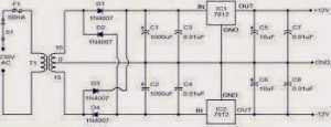
12V Dual Power Supply Circuit Diagram | 7812 Voltage Regulator Circuit

7812 Voltage Regulator Circuit

The 7812 is a three-terminal linear voltage regulator integrated circuit (IC) that provides a fixed regulated output voltage of 12V. It is commonly used in power supplies and voltage regulation applications, where the input voltage can fluctuate and a stable output voltage is required. The 7812 operates on a wide input voltage range, typically 10V to 35V, and can provide a maximum output current of 1A.

The 7812 IC is a positive voltage regulator which means that it generates a positive voltage with respect to the common ground. 12 volts dc supply is maintained by using regulator 7812 IC, if the supply voltage exceeds 12 volts then regulator IC 7812 blocks excessive voltage. This power supply circuit is used for pure dc voltage requirement devices like audio systems low voltage ripples dc voltage waveform found.


DC 12 VOLTS POWER SUPPLY CIRCUIT

12V Dual Power Supply Circuit Diagram


12V power supply circuits with output voltages around 12V, LM7912 is a negative voltage regulator used for regulating negative voltages. These are specially designed to regulate negative voltages. These are designed with the lowest noise and highest power supply rejection ratio. The output voltage of LM7912 is -12V

Voltage Regulator

The voltage regulator is an important part of electronics. It allows devices to adjust the voltage level so that it’s consistent, regardless of how much power is being drawn. This prevents devices from exploding and helps make circuits run more efficiently. The secondary function of voltage regulation is to prevent noise — excess voltage — from entering a circuit.

7812 IC Pinout


7812-pinout


7812 IC Datasheet Pdf Download

if the above link is not open please check the below link

https://drive.google.com/file/d/1MmGcnttO4bs5ebFQHO-BWjHuYBaH5WiY/view?usp=sharing

7812 IC Price

If you want to purchase this 7812 IC please refer to the following website

Corslet Soldering Tool Kit

How to Make AC to DC (12V-0-12V) Dual Power Supply Circuit using Transformer


Sunday, February 5, 2023

What is SCR? | Turn ON methods of SCR or Triggering Method of SCR

The Turn ON Method of SCR is the most important part of the correct function of the device. There are many different ways to trigger the SCR. This article will explain some of the more popular methods.

What is SCR?

SCR or silicon-controlled rectifier is a four-layer solid-state device. The SCR can be used as an ON/OFF switch for AC or DC signals. The device consists of a PN junction with two gate electrodes attached to it. When the gate voltage is below a certain value, the SCR is turned OFF. When the gate voltage is increased above this value, the SCR turns ON.

Turn ON methods of SCR

turn ON method of SCR

Turn On Methods of SCR

There are two ways to turn ON an SCR or silicon-controlled rectifier. The first is to use a gate voltage, and the second is to use a current.

Using a gate voltage is the most common method, and it is done by applying a voltage to the gate terminal of the SCR. This creates a field in the depletion region that turns on the SCR.

The other way to turn ON an SCR is by using a current. This is done by passing a current through the anode and cathode terminals of the SCR. This creates a magnetic field that turns on the SCR.

The Different Types of Triggering Methods for SCR

There are four different ways to trigger an SCR or silicon-controlled rectifier.

  • The first is called gate trigger, whereby a small current is passed through the gate leads to creating a voltage drop.
  • The second is called cathode trigger, and uses a similar method but with the voltage drop happening between the cathode and anode.
  • The third is called the anode trigger, which uses a reverse current flow to cause the voltage drop.
  • And finally, there is the base trigger, which employs a transistor to create the voltage drop.

Conclusion

There are several methods that can be used to turn on an SCR device, and the best method for any given application depends on the specific requirements of that application. In general, though, the most common methods for turning on an SCR are through a voltage or current trigger. If you need help determining which method is best for your application, please contact us and we will be happy to assist you.

Saturday, February 4, 2023

5.1 Prologic Board price | B-Tech Audio DTS Board, Dolby pro logic board

5.1 Prologic Board

5.1 Prologic board or 5.1 Pre Amp Kit Audio Board and Convert 2 Channel to 5.1 Channel and also use for Home Theatre Sound Recorder and Sound Circuits. This is a high-quality DTS 5.1 Prologic Board, A surround sound decoder that converts stereo input to 5.1 Channel like the front left, front right, center, rear left, rear right, and sub. It’s a pre-amp board with hi-fi audio output. Connect with a good amplifier to get the best result for individual channel crystal clear audio.

Technical Specifications of 5.1 Prologic Board

  1. 5.1 Input/2.1 Input ( by selection switch)
  2. Power input 12 0 12 dual supply 1 amp
  3. Subwoofer Out, Surround Out, and L & R out with built-in Bass Treble

B-Tech Audio DTS 5.1 Prologic Board

5.1 prologic board

The purchase Link  given below

B-Tech Audio DTS 5.1 Channel Remote Kit Small Display Working with (12-0-12v) AC Supply

This B. Tech audio DTS board works with a 12-0-12v AC supply no need to buy a DC rectifier it comes with an inbuilt Rectifier with regulator ICs like 7805 this 5.1 Dts board comes with the remote kit along with a 5.1 Channel Input Option With Encoder Functions. 16 * 2 Jumbo Display Used Original Japan ICs and  6 Channel Independent electronic Volume (0 to -99Db/1Db step-00Db), 6 Channel Independent Gain Control (0 Db To +14 Db Step), L/R Channel 4 Input Selector (Input Gain 0 to +14 Db/2Db Step, Multi-Channel Input -6 Channel Input, Tone Control Bass-14 to + 14 Db (2 Db Step)Treble- 14 to +14 Db ( 2 Db Step), Working Voltage AC Transformer 12-0-12v 1Amps.


B.tech 5.1 DTS board

B-Tech Audio DTS 5.1 Channel Remote Kit

Related:

  • crystal 5.1 Prologic board price
  • 5.1 Prologic board with remote kit
  • crystal audio 5.1 Prologic board price in India
  • Vasanth 5.1 Prologic board
  • maharaja 5.1 Prologic board
  • Sakthi 5.1 amplifier board price
  • Prologic board circuit diagram
  • 5.1 surround board
  • Dolby pro logic board

Purchase Links:

HD Audio Rush DTS / AC3 5.1 Channel https://amzn.to/3gNHGrS

B-TECH Audio BASS Treble and Tone Control Board. https://amzn.to/3oK80HJ

B-Tech Audio 5.1 Prologic Board. https://amzn.to/362TSTh

Audio Amplifier Cabinet. https://amzn.to/3gJIWfB

Friday, February 3, 2023

Youtube How to Post Shorts | Where to Upload Youtube Shorts

Youtube Shorts

youtube how to post shorts

To post a short video on YouTube, follow these steps:

  1. Sign in to your YouTube account.
  2. Click on the camera icon in the top right corner.
  3. Select “YouTube Shorts” from the list of options.
  4. Record your video or select a video from your camera roll.
  5. Add music, effects, or text to enhance your video if desired.
  6. Choose a thumbnail for your video.
  7. Add a title and description.
  8. Choose privacy settings and select the audience you want to share your video with.
  9. Click “Publish” to post your short video on YouTube.

Note: To use YouTube Shorts, you’ll need to have a YouTube account and be in a location where Shorts are available.

Here are some additional tips to help you get the most out of your YouTube Shorts experience:

  1. Keep your videos short and to the point: YouTube Shorts are meant to be brief, attention-grabbing videos, so aim for 15 seconds or less.
  2. Make use of the editing tools: YouTube Shorts comes with a variety of editing tools, such as filters, text overlays, and music, to help you enhance your videos and make them stand out.
  3. Choose music that complements your video: Select music that fits the mood and tone of your video, and make sure it’s not too distracting.
  4. Be creative with your content: Try to be creative and unique with your videos to make them stand out. Experiment with different formats, such as stop-motion or time-lapse, and see what works best for you.
  5. Share your videos on social media: After posting your video on YouTube, share it on your other social media platforms to reach a wider audience.
  6. Engage with your viewers: Encourage comments and interaction on your videos by asking questions or starting a conversation. Respond to comments and show your viewers that you’re active and engaged.
  7. Analyze your performance: Keep an eye on your video’s performance by checking the analytics in your YouTube Studio. Use this information to improve your content and grow your following.

Where to Upload Youtube Shorts

YouTube Shorts can be uploaded to the YouTube Shorts section of your YouTube channel. To access this section, open the YouTube app on your mobile device, tap on the camera icon located in the right bottom corner, select the “YouTube Shorts” option, and start creating and uploading your short videos.

To create and upload a YouTube Short, you’ll need to follow these steps:

  1. Open the YouTube app on your mobile device.
  2. Tap on the camera icon located in the right bottom corner.
  3. Select the “YouTube Shorts” option.
  4. Choose the camera mode you prefer to use: “Normal” or “Music.”
  5. Record your video, which can be up to 60 seconds in length.
  6. You can add music, text, filters, and other elements to enhance your video.
  7. Preview your video and make any necessary edits.
  8. Add a title and description for your video.
  9. Select the privacy settings for your video: Public, Unlisted, or Private.
  10. Finally, tap on the “Publish” button to upload your YouTube Short to your channel.

Note that YouTube Shorts are currently only available on the YouTube app on mobile devices, and not on the desktop website.

Thursday, February 2, 2023

AC to DC Converter 12V Circuit Diagram, 220v to 12v DC Converter Circuit

AC to DC 12V Converter Circuit

In this article I discuss AC to DC Converter 12v Circuit, here there are mainly two types of converters widely used for AC-DC conversion purposes. The traditional transformer-based linear converter uses a simple diode bridge with a capacitor voltage regulator.

An AC to DC 12V converter is a device that converts Alternating Current (AC) to Direct Current (DC) with a voltage output of 12V. This is useful in applications where a DC voltage source is required, but only an AC source is available. The converter is typically used in automotive, industrial, and household applications.

A simple Diode Bridge can be constructed either with a single semiconductor device like DB107 or with 4 independent diodes like 1N4007. The other type of converter is SMPS (Switch mode power supply) which uses a high-frequency small transformer and a switching regulator to produce DC output.

In traditional Transformer-based design, we are using simple diodes and capacitors to convert the Alternating current into Direct Current. An optional voltage regulator to regulate the output DC voltage from AC. The project will be an AC-DC converter using a Transformer with an input voltage of 230V or 220V and an output of 12V, 1A.

Also Read: Difference Between AC and DC Currents | AC and DC Waveforms

220v to 12v dc converter circuit diagram

AC to DC Converter 12v

220v to 12v dc converter circuit diagram
220v to the 12v dc converter circuit diagram

The above 220V to 12V DC Converter Circuit is simple, and the transformer is used to reduce the AC voltage. Four general-purpose 1N4007 diodes are used in this circuit to rectify the AC input by connecting the bridge, also known as the Bridge Rectifier. 1N4007 has a peak repetitive reverse voltage of 1000V and an average rectified forward current of 1A. These four diodes are used to convert the alternating current voltage to the direct current voltage. Actually, the transformer’s output is probably around 13V AC (unregulated), which is fed to the bridge rectifier to generate DC voltage. The diodes are used to build a bridge converter, which is an essential component of the 12v AC to DC converter circuit, in the circuit shown in the figure

What Is Bridge Rectifier

A bridge rectifier is a device that converts AC to DC electricity. It is used in many home appliances such as air conditioners, washers, dryers, and even some power tools. The bridge rectifier is a DC-DC converter that converts input AC to a lower DC voltage, which may be used for power input to a load

AC to DC Converter Circuit Working:

A step-down transformer is used to convert the high voltage AC to the low voltage AC. The transformer is PCB mounted and it is a 1-ampere 13-volt transformer. However, during the load, the transformer voltage drops approximately 12.5-12.7 volt.

The essential part of the circuit is a diode bridge which consists of four diodes. The diode is an electronic semiconductor device that converts the alternating current to a direct current.

AC to DC Converter Device Name

The device used to convert AC to DC is a Rectifier. As the name suggests, the rectifier corrects or straightens the direction of the current. The device periodically reverses the direction of alternating current (AC) to direct current (DC), which usually flows in one direction.

Components Required for AC to DC Converter 12V Circuit

  •  Transformer with 1A 13V Rating
  •  4 No.s – 1N4007 Diodes
  •  A 1000uF Electrolytic capacitor with a 25V rating.
  •  Few single strand wires
  •  Breadboard
  •  LDO or a Linear Voltage Regulator as per specification (Here LM2940 is used).
  •  A multimeter to measure the voltage.

220v to 12v AC to DC converter Circuit using 7812 IC

Limitations of Transformer-based AC to DC Converter Circuit

Transformer-based AC to DC conversion is a common choice where DC is required but it has certain drawbacks.

  • In any situation where the input AC voltage has the possibility to fluctuate or if the AC voltage drops significantly, the output AC voltage across the transformer also gets dropped. So a 230V AC to 12V DC converter cannot be powered in a 110V AC line. To address this issue, an additional setting is provided for different input voltage levels.
  • Despite not having a universal input voltage range, it is a costly choice, as the transformer itself costs more than 60% of the total manufacturing cost of the converter circuit.
  • Another limitation is low conversion efficiency. The transformer gets heated up and wastes unnecessary energy.
  • The Transformer is heavy stuff which unnecessarily increases the weight of the product.
  • Due to the transformer, a bigger space is required inside the product to fit the converter circuit or at least the transformer.

Different Types of AC to DC Converters

We already know that AC to DC converters is also known as rectifiers, in this section, we will discuss uncontrolled rectifiers, of which there are four types…

Single-phase half wave rectifier

Single phase full-wave bridge rectifier

Single-phase center tapped full wave rectifier

Three phases half-wave diode rectifier

Single Phase Half wave Controlled Rectifier

In a single-phase half-wave rectifier, the negative or positive half of the AC voltage flows, while the other half of the AC voltage is blocked. Therefore, the output receives only half of the AC wave. here a single diode is enough for this rectification.

single phase half wave rectifier

Single-phase half-wave rectifier Circuit

During the positive half cycle, the diode is in forwarding bias condition and maintains current up to RL (load resistance). A voltage is developed across the load, which is similar to the input AC signal of a positive half cycle.

Single-phase full-wave bridge rectifier

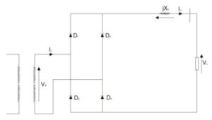
The single-phase full-wave rectifier does this by using four diodes arranged in a bridge arrangement passing the positive half of the waveform as before but inverting the negative half of the sine wave to create a pulsating DC output.

Single-phase-full-wave-bridge-rectifier

Single-phase-full-wave-bridge-rectifier circuit

single-phase full-wave diode rectifiers contain the following important parameters from Industrial Datasheet

  • Peak repetitive reverse voltage VRRM;
  • Ripple factor;
  • RMS input voltage per transformer leg VS;
  • Diode average current IF(AV);
  • Rectification ratio;
  • Output ripple frequency fr;
  • Peak repetitive forward current IFRM;
  • Transformer rating primary VA;
  • Diode RMS current IF(RMS) ;
  • Form factor;
  • Transformer rating secondary VA;
  • The form factor of diode current IF(RMS)IF(AV).

Single-phase Center Tapped full-wave rectifier

Read also: 12v to 5v DC-DC Converter Circuit Diagram | 12V to 5V Converter using 7805 IC

To overcome these limitations, SMPS or switch mode power supply is a preferable choice.

220V AC to 12V DC Converter Price:

Tags: 220/230v AC to 12v, 220v AC to 12v DC circuit Diagram, 220v ac to 5 v dc, 230v ac to 5 v dc regulated power supply circuit, 5v DC converter circuit diagram, ac to dc converter 12v, ac to dc supply circuit, ac to dc voltage regulator circuit, Bridge Rectifier circuit Diagram, circuit diagram of regulated power supply, how to convert ac to dc, how to make 220v ac to 12v dc, how to regulate voltage Regulated dc power supply, Regulated DC Power supply circuit, regulated voltage circuit diagram, voltage regulator using 7805, voltage regulator using 7812.

LCD Full Form, what is LCD?

What is LCD?

In this tutorial, I would like to Explain about LCD and LED, what is the difference between LCD and LED. LCD Full Form and LED Full-Form are clearly explained in detail on this website Circuits99.com.

This article is a detailed explanation of what an LCD is and how it works. It also goes over the different types of LCDs, their applications, and the components used to make them. The article also includes a link to a practical demonstration that uses a Liquid Crystal Display. This article is intended for those with a basic understanding of electronics who wants to learn more about the inner workings of an LCD.

The LCD (liquid-crystal display) was one of the first displays that were used in computers and TVs. The LCD uses liquid crystals instead of electric charges to change the way light is reflected on a screen, which allows for much more vivid, life-like images. These displays are known for their thin, energy-efficient screens and long product lifespans, making them a must-have in modern technology. However, the LCD has had a very interesting and sometimes controversial history, which is the focus of this article.

LCD Full Form

LCD stands for Liquid Crystal Display. LCDs are flat panel display technology and are used as screens in TVs and computer monitors, At present LCDs, are used in mobile phones also. These LCDs are completely different from that old CRT displays, it uses liquid crystals instead of cathode ray in their primary form of operation.

What is LCD?

LCD screen

LCD Screen Working

The LCD display has millions of pixels which are made up of liquid crystals and arranged in a rectangular grid. Each pixel has a Red, Green, and Blue, often called RGB that can be turned On or Off. These sub-pixels are turned off in that case Black screen appears. when all the sub-pixels are turned On 100%, in that case, the screen gets white.

The LCD works on a combination of two states of matter, which are solid and liquid. The LCD consists of two layers they are polarized panels like filters and electrodes. The solid part is crystal and liquid and crystal together make a visible image. The LCD screen picture appears by blocking the light rather than emitting the light. The LCD has two types of pixel grids.

Advantages of LCD

  • It has a low cost
  • Less power consumption and energy efficiency.
  • LCD monitors have less radiation than CRT monitors.
  • LCDs provide excellent contrast, brightness, and resolution as compared with CRTs.

Disadvantage of LCD

  • LCDs are less reliable displays.
  • LCD requires a backlight for lighting the pixels.
  • When in a low-intensity level of light, the LCD color saturation is reduced.
  • LCDs are fixed in resolution and ratio.


Wednesday, February 1, 2023

Bluetooth Speaker Circuit Board Kit | Bluetooth speaker board

Bluetooth speaker board

A Bluetooth speaker board refers to a printed circuit board (PCB) with Bluetooth functionality that enables audio playback from Bluetooth-enabled devices such as smartphones, laptops, and tablets. This board includes components such as Bluetooth chips, amplifiers, and audio codecs, which are responsible for receiving and processing audio signals and driving speakers to produce sound. Some popular brands that make Bluetooth speaker boards include Texas Instruments, Cirrus Logic, and NXP.

What is Bluetooth Circuit Board

The Bluetooth circuit board is the unseen performer that connects your audio device and headset, allowing you to listen to your favorite songs. Thanks to the Bluetooth PCB, you can also use voice signals to communicate over the Bluetooth connection.

Bluetooth Speaker Circuit Board Kit

bluetooth speaker circuit board kit

Bluetooth circuit board kit

The Bluetooth Speaker Circuit Board consists of Bluetooth FM, USB, AUX, Card MP3 Stereo Audio Player, Decoder Module Kit for Amplifier Board. Bluetooth Amplifier Board kit used for Bluetooth Speaker DIY for audio amplifiers.

Bluetooth Speaker Circuit Applications

Applications of Bluetooth circuit boards are

  1. Wireless Headsets and Earphones
  2. Bluetooth Speakers
  3. Multimedia Transfer
  4. Automatic Synchronization

Bluetooth speakers are all the rage these days, and everyone has one. The Bluetooth circuit board is built into the main circuit board of the wireless speakers and is responsible for syncing with your audio player or smartphone.

Bluetooth speaker circuit kit

Bluetooth speaker boards can come in different sizes and specifications, depending on the intended application and target market. For example, some boards are designed for portable speakers and offer compact form factors and low power consumption, while others are aimed at high-end home theater systems and offer advanced audio processing capabilities and multiple channels for multi-room audio.

Overall, Bluetooth speaker boards have become a popular solution for building speakers due to their ease of use and versatility, allowing users to stream music wirelessly from a variety of devices without the need for cords or cables.

IR Sensor Module Working with Arduino

IR Sensor Module Working Introduction Introduction : Start with a brief introduction to the IR Sensor Module and its applications. Mention t...