

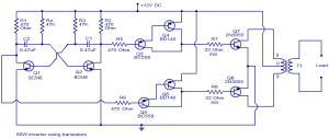
60W-100W Inverter using Transistors
The 60W-100W Inverter using Transistors circuit diagram of a fully transistorized inverter that can drive up to 60W loads. Transistors Q1 and Q2 form a 50Hz astable multivibrator. The output from the collector of Q2 is connected to the input of the Darlington pair formed by Q3 and Q4.
60W-100W Inverter using Transistors
Similarly, the output of Q1 is coupled to the input of the pair Q5 and Q6. The output from the Darlington pairs drive the final output transistors Q7 and Q8 which are wired in the push-pull configuration to drive the output transformer.
Read more: 100 Watt Inverter Circuit using IC CD4047 and MOSFET
About Inverter Circuit
The circuit can be assembled on a Vero board.
T1 can be a 230V primary to 9-0-9V, 6A secondary transformer.
Transistors Q4, Q6, Q7, and Q8 must be fitted with heat sinks.
Use a 12V, 7Ah battery for powering the inverter.
Slight adjustments can be made on the value of R3 and R4 to get exact 50Hz output.