
LCD Interfacing with 8051 Microcontroller

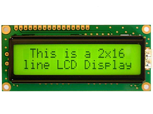
16×2 LCD
An LCD (liquid crystal display) is a display device that is made of a thin layer of crystal material sandwiched between two sheets of glass. It is an electronic device that is used for displaying text and images. Interfacing an LCD to a microcontroller is a very simple process. In this tutorial, we will learn about the basics of interfacing an LCD to a microcontroller, using an 8051 microcontroller.
I am going to explain how to interface the LCD module with 8051 microcontrollers using many easy-to-understand example codes. I will be using a 16×2 LCD module in this article for demonstration purposes. Let’s get started. I will be using the MsBlink library for my 8051 projects.
LCD is an inevitable part of most of all embedded projects. It is used to display various information to the user. In this article, we are going to learn how to interface a 16×2 LCD with an 8051 microcontroller. Many of the assemblers find it difficult to interface an LCD with their microcontroller.
Which can divide into five categories, Power Pins, contrast pins, Control Pins, Data pins, and Backlight pins
| Category | Pin NO. | Pin Name | Function |
| Power Pins | 1 | VSS | Ground Pin, connected to Ground |
| 2 | VDD or Vcc | Voltage Pin +5V | |
| Contrast Pin | 3 | V0 or VEE | Contrast Setting, connected to Vcc through a variable resistor. |
| Control Pins | 4 | RS | Register Select Pin, RS=0 Command mode, RS=1 Data mode |
| 5 | RW | Read/ Write pin, RW=0 Write mode, RW=1 Read mode | |
| 6 | E | Enable, a high to low pulse need to enable the LCD | |
| Data Pins | 7-14 | D0-D7 | Data Pins, Stores the Data to be displayed on LCD or the command instructions |
| Backlight Pins | 15 | LED+ or A | To power the Backlight +5V |
| 16 | LED- or K | Backlight Ground |
RS: RS is the register select pin. We need to set it to 1 if we are sending some data to be displayed on LCD. And we will set it to 0 if we are sending some command instruction like clear the screen (hex code 01).
RW: This is a Read/write pin, we will set it to 0 if we are going to write some data on LCD. And set it to 1, if we are reading from the LCD module. Generally, this is set to 0, because we do not have a need to read data from LCD. Only one instruction “Get LCD status”, needs to be read sometimes.
E: This pin is used to enable the module when a high to low pulse is given to it. A pulse of 450 ns should be given. That transition from HIGH to LOW makes the module ENABLE.
There are some preset command instructions in LCD, we have used them in our program below to prepare the LCD (in lcd_init() function). Some important command instructions are given below:
16×2 LCD module commands
| Command | Function |
| 0F | LCD ON, Cursor ON, Cursor blinking ON |
| 01 | Clear screen |
| 02 | Return home |
| 04 | Decrement cursor |
| 06 | Increment cursor |
| 0E | Display ON, Cursor blinking OFF |
| 80 | Force cursor to the beginning of 1st line |
| C0 | Force cursor to the beginning of 2nd line |
| 38 | Use 2 lines and a 5×7 matrix |
| 83 | Cursor line 1 position 3 |
| 3C | Activate the second line |
| 08 | Display OFF, Cursor OFF |
| C1 | Jump to a second line, position1 |
| OC | Display ON, Cursor OFF |
| C1 | Jump to a second line, position1 |
| C2 | Jump to a second line, position2 |
LCD Interfacing with 8051 Microcontroller Circuit Diagram
A circuit diagram for LCD interfacing with 8051 microcontrollers is shown in the below figure. All the connections as per the diagram.

// Program for LCD Interfacing with 8051 Microcontroller (AT89S52)
#include<reg51.h>
#define display_port P2 //Data pins connected to port 2 on microcontroller
sbit rs = P3^2; //RS pin connected to pin 2 of port 3
sbit rw = P3^3; // RW pin connected to pin 3 of port 3
sbit e = P3^4; //E pin connected to pin 4 of port 3
void msdelay(unsigned int time) // Function for creating delay in milliseconds.
{
unsigned i,j ;
for(i=0;i<time;i++)
for(j=0;j<1275;j++);
}
void lcd_cmd(unsigned char command) //Function to send command instruction to LCD
{
display_port = command;
rs= 0;
rw=0;
e=1;
msdelay(1);
e=0;
}
void lcd_data(unsigned char disp_data) //Function to send display data to LCD
{
display_port = disp_data;
rs= 1;
rw=0;
e=1;
msdelay(1);
e=0;
}
void lcd_init() //Function to prepare the LCD and get it ready
{
lcd_cmd(0x38); // for using 2 lines and 5X7 matrix of LCD
msdelay(10);
lcd_cmd(0x0F); // turn display ON, cursor blinking
msdelay(10);
lcd_cmd(0x01); //clear screen
msdelay(10);
lcd_cmd(0x81); // bring cursor to position 1 of line 1
msdelay(10);
}
void main()
{
unsigned char a[15]=”CIRCUIT DIGEST”; //string of 14 characters with a null terminator.
int l=0;
lcd_init();
while(a[l] != ‘\0’) // searching the null terminator in the sentence
{
lcd_data(a[l]);
l++;
msdelay(50);
}
}