Potential Transformer
The Potential Transformer is a passive electromagnetic device that works on the principle of electromagnetic induction, which transfers electrical energy magnetically from one circuit to another. It has two coils which are one primary and one secondary. The two windings (coils) are magnetically connected to each other without any magnetic core and are electrically separated.
The transformer transmits electrical energy (voltage/current) from one winding to another winding (coil) by mutual induction. The transformer transfers the electrical power from one winding to another winding without changing the frequency. Transformers are classified into two types based on the structure of the core, such as core-type transformers and shell-type transformers. These are step-up transformers and step-down transformers. Different types of transformers are used in AC circuits, such as power transformers, potential transformers, three-phase transformers, and autotransformers.
What is a Potential Transformer?
A potential transformer is a step-down transformer that lowers the voltage of a high voltage circuit to a low level to measure it. These are connected through or in parallel to the monitored line.
An electromagnetic device used to convert a high voltage of a circuit into a low voltage is called a potential transformer. The output of a low voltage circuit can be measured with voltmeters or wattmeters. These can increase or decrease the voltage levels of the circuit, without changing its frequency and windings. Working principle, the structure of potential transformer is the same as the power transformer and conventional transformer.
Potential Transformer Symbol

Potential Transformer Symbol
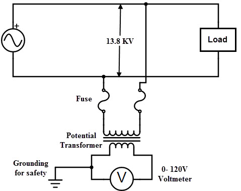
Potential Transformer Circuit Diagram

Potential Transformer Circuit Diagram
Potential Transformer Working
A potential transformer connected to the power circuit on which the voltage is to be measured is connected between phase and earth by using a voltmeter. That is, the primary winding of the potential transformer is connected to the high voltage circuit, and the secondary winding of the transformer is connected to the voltmeter. Due to mutual excitation, the two windings are magnetically attached to each other and act on the principle of electromagnetic induction.
According to the convention transformer, the transformation ratio is V1/V2 = N1/N2
V2 = V1N2/N1
‘V1’= voltage of the primary winding
‘V2’ = voltage of the secondary winding
‘N1’= number of turns in the primary winding
‘N2’= number of turns in the secondary winding
Types of Potential Transformers
These are classified into outdoor and indoor potential transformers
1. Outdoor Potential Transformers
2. Indoor Potential Transformers
Outdoor Potential Transformers
There can be single or 3-phase potential transformers that are available for different ranges of operating voltages which are used for outdoor relaying and metering applications.
Electromagnetic or Wound Type Conventional Potential Transformer
These are Up to 33KV, these are of electromagnetic type single and three-phase voltage transformers are used.
33KV single-phase outdoor potential transformers can be two types electromagnetic type and capacitive voltage transformer (CVT) are used.
Indoor Potential Transformers
They are also available as single-phase or three-phase mold and magnetic type PTs. The mounting mechanism can be of the fixed or withdrawable type. In these types of PT, all parts of the primary winding are isolated from the earth with their rated insulation capacity. These are designed to operate relays, measuring instruments, and other control devices in the indoor service with high accuracy.
Applications of Potential Transformers
- Used for the protection of impedance in the generators
- Used in Distance protection of feeders
- Used in synchronization of generators and feeders.
- For Electrical protection systems
- Used for Electrical Metering systems
- Used as protection voltage transformers
- Uses in power line carrier communication circuits

