
What is a Diode?
In this article, we discuss what is Diode and its Applications of Diodes and where we can use it. A diode is an electronic component that can be used to control the flow of electricity. It has two terminals, an anode, and a cathode. The purpose of the diode is to allow current to flow in one direction but not the other. The components that make up a diode are the anode, cationic, cathode, and passivated film.

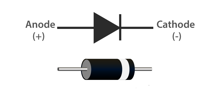
Diode Symbol
Generally, the diode is made with semiconductor materials like P and N namely Anode and Cathode are the two terminals. The diode having Forward bias and Reverse bias depends on the type of voltage applied which is positive and negative.
Forward Bias: When the applied voltage to the anode is positive with respect to the cathode and the diode is in Forwarding Bias. The diode will conduct when the voltage applied to the diode is greater than the threshold level generally says o.6v for silicon diodes and 0.7V for germanium Diodes. In this condition, the diode will act as a short circuit and allow the current to flow through the diode.
Reverse Bias: When the Voltage applied to the cathode is positive with respect to the anode, then the diode said to be in reverse bias is done by the polarity of the diode is changed. In this condition, the diode will act as an open circuit, and it doesn’t allow the current to flow through the diode.
Types of Diodes
Various types of diodes available in the market you can choose depend on the electronic design, here various types of diodes used depend upon the different types of applications. they are,
P-N Junction Diode
Rectifier Diode
Schottky Diode
Light Emitting Diode
Photo Diode
Laser Diode
Zener Diode
Tunnel Diode
Silicon Controlled Rectifier
Vacuum Diode
Applications of Diodes
Diodes are used in a wide variety of applications to control the flow of electricity. In the simplest sense, diodes can be used to prevent current from flowing in one direction, while allowing current to flow in the opposite direction. This is how diodes are used in battery backup systems to prevent electricity from flowing to your home when the power is off. Diodes can also be used to detect when current is flowing, such as with burglar alarms and motion detectors.
As per Applications of Diodes can be Achieved by the following circuits,
- Rectifiers
- Clipper Circuits
- Clamping Circuits
- Reverse Current Protection Circuits
- In Logic Gates
- Voltage Multipliers
Rectifier
Generally, the Diode is used for the rectification of AC power into DC power, using these diodes we can build different types of rectifier circuits. The most common type of rectifier circuits are Fullwave, half-wave, Center tapped, and full-bridge rectifier circuits. You can find below the diode operation as a rectifier.
Halfwave Rectifier

Halfwave Rectifier
From the above waveform during the positive cycle the input is given to the anode of the diode with the respective cathode, so the diode is forward biased already discussed above and in that case current flowing to the load. The voltage across the load is the same as the supply voltage.
During the negative half-cycle of the input given to the anode of the diode with respect to the cathode, there is no current flowing to the load, this is reversely biased in that case, there is no current flowing to the load. This is an open circuit and no voltage shows across the load. Both voltage and current at the load side are of one polarity means the output voltage is pulsating DC. If you want to get continuous DC without any ripples you should use a capacitor that is connected across the load.
Clipper Circuits
Clipping Circuits consist of a diode and resistor. These circuits are widely used in FM transmitters, where the excessive noise peaks are removed by using these clipper circuits.
Clippers may be classified into two types based on the placement of the diode.
- Series Clippers
- Shunt Clippers
Series Clippers

The above figure shows the positive series clipper circuit the diode connected to input in reverse bias the positive half cycle clipped in output voltage waveform. In the positive series, clipper output kept zero due to the diode connected in reverse bias, during the positive half-cycle.
Hence, the positive half cycle of the out waveform was removed. during the negative half-cycle, the diode conducts because the diode is in a forward direction the voltage appears in the output waveform.
Shunt Clippers
In a positive shunt clipper circuit, the diode is shunted across the output, from the above circuit during the positive half cycle the diode is forward biased so the output voltage gets zero due to the diode acting as a closed switch.
During the negative half cycle, the diode is reverse biased and acts as an open switch so the output will appear in the waveform. the above both series and shunt clipper positive half cycle is clipped in the output waveform.
Clamping Circuits
What is a Clamper? Clamping Circuit provides an important role in output waveform and is used to shift either the positive or negative peaks of the input signals to a required level. This clamping circuit can be used as negative or positive which depends on the diode configuration. this circuit is also called a level shifter or DC restorer.
Here clamper circuits classified into two types they are,
- Positive Clamper circuit
- Negative clamper Circuit
Positive Clamper Circuit
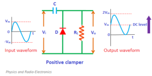
Positive Clamping Circuit that changes the DC level of a signal to the desired level without changing the shape of the applied signal. If the circuit pushes the signal upwards then the circuit is called a positive clamper. When the signal is pushed upwards, the negative peak of the signal gets the zero level.
Negative Clamper Circuit

A negative Clamping Circuit opposite of a positive clamper, if the circuit pushes the signal downwards then the circuit is said to be a negative clamper. When the signal is pushed downwards, the positive peak of the signal meets the zero level.
These clamping circuits can be positive or negative depending on the diode configuration
Also Read: What is Clamper Circuit?