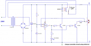
Battery Charge Controller Circuit
The charge controller circuit for the battery does not bother you when you worry about changing the charger with different battery levels, the main advantages are an improved lifetime and low power consumption since it turns off the charger when the battery is fully charged. So far, we have published a simple battery charge controller circuit using 555 IC, where many of our readers commented that they found it difficult to set threshold levels and also that it seemed more difficult to analyze the operation of the threshold.
Read Also: 24v lead acid battery charger circuit diagram
Battery Charge Controller Circuit by LM324 Comparator IC

Battery Charge Controller Circuit Diagram
Components Required:
- LM324 IC
- Zener diode 5.1V
- Bridge IC/1N4007X4
- Diode 1N4007
- Transistor BC548X2
- Led Green
- Capacitor 1000uF
- Resistor 1KX4, 100K
- Pot 50K/47K
- Relay 12V/10A
- Transformer 0-15V/2A
LM324 Pinout Diagram

LM324 Pin Description
| Pin# | Pin Name | Pin Description |
|---|---|---|
| 1 | Output 1 | The output of IC’s First Operational Amplifier |
| 2 | Input1(-) / Inverting Input 1 | Inverting Input of IC’s First Operational Amplifier |
| 3 | Input1(+) / Non Inverting Input 1 | Non-Inverting Input of IC’s First Operational Amplifier |
| 4 | Vcc / Positive Supply | Positive Supply of IC / Positive Supply of All Operational Amplifiers. |
| 5 | Input1(-) / Inverting Input 2 | Inverting Input of IC’s Second Operational Amplifier |
| 6 | Input1(+) / Non Inverting Input 2 | Non-Inverting Input of IC’s Second Operational Amplifier |
| 7 | Output 2 | The output of IC’s Second Operational Amplifier |
| 8 | Input1(-) / Inverting Input 3 | Inverting Input of IC’s Third Operational Amplifier |
| 9 | Input1(+) / Non Inverting Input 3 | Non-Inverting Input of IC’s Third Operational Amplifier |
| 10 | Output 3 | The output of IC’s Third Operational Amplifier |
| 11 | Ground (GND) | Ground / Negative Supply of IC / Negative Supply of All Operational Amplifiers. |
| 12 | Input1(-) / Inverting Input 4 | Inverting Input of IC’s Forth Operational Amplifier |
| 13 | Input1(+) / Non Inverting Input 4 | Non-Inverting Input of IC’s Forth Operational Amplifier |
| 14 | Output 4 | The output of IC’s Forth Operational Amplifier |
LM324 IC Features| LM324 IC Technical Specifications
- LM324 IC has Four high gain operational amplifiers in a single package.
- The DC gain of each op-amp is 100dB.
- All four op-amps can be operated from a single supply.
- It is Operated from a wide supply voltage from 3V to 32V.
- It has Input and output are protected from overload.
- It can take on a very low operating current drain 700uA to 800uA
- The maximum bandwidth is 1MHz.
- The IC can be easily used with logic devices and microcontrollers.
- Having internally short circuit protected.
Applications of LM324 IC Comparator
- Used in Sensor Circuits
- Used in Small Signal Amplification
- Widely used in General Operational Amplifiers Circuits
- used for Audio preamplifiers
- Filters
- And also used in Comparator Applications
LM324 IC Datasheet Download
Here you can download the datasheet of the LM324 IC link given below I just copy and paste a link
https://pdf1.alldatasheet.com/datasheet-pdf/view/212589/NSC/LM324.html

