Half Wave Rectifier
A half–wave rectifier is a type of electronic circuit that converts an alternating current (AC) signal into a pulsating direct current (DC) signal. It works by allowing current to flow through the circuit in only one direction, which results in the elimination of the negative portion of the AC signal.
Half Wave Rectifier Diagram

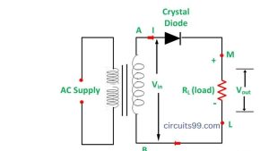
Half Wave Rectifier Circuit
The basic circuit of a half-wave rectifier consists of a diode, a load resistor, and a source of AC signal. The diode is connected in series with the load resistor and is oriented so that current can only flow in one direction, which is determined by the polarity of the AC signal.
Half Wave Rectifier Working
During the positive half cycle of the AC signal, the diode allows current to flow through the circuit and the load resistor, resulting in a positive voltage across the load resistor. During the negative half cycle, however, the diode blocks current flow and there is no voltage across the load resistor.
The output of the half-wave rectifier is a pulsating DC voltage that consists of a series of positive pulses with a period equal to the period of the AC signal. The amplitude of the DC voltage is equal to the peak value of the AC signal minus the forward voltage drop of the diode.
Half-wave rectifiers are commonly used in low-power applications where the efficiency of the circuit is not a critical concern. They are often used in simple power supplies, battery chargers, and voltage regulators.
Half Wave Rectifier Formula
The output voltage of a half-wave rectifier can be calculated using the following formula:
Vout = Vpeak * |sin(ωt)|
Where:
- Vout is the output voltage
- Vpeak is the peak value of the input voltage
- ω is the angular frequency of the input voltage (ω = 2πf, where f is the frequency of the input voltage)
- t is the time
The absolute value of the sine function is used to ensure that the output voltage is always positive, as the diode in a half-wave rectifier only allows current to flow in one direction

